Technical solutions to ensure reliability levels in rural electricity networks of 10 and 0.38 kV
Diagrams of rural electricity networks
Rural electrical networks consist of 35 or 110 kV, transformer substations with voltages of 110/35, 110/20, 110/10 or 35/6, power lines with voltages of 35, 20, 10 and 6 kV, consumer transformer substations 35/ 0.4, 20/0.4, 10/0.4 and 6/0.4 kV and lines with a voltage of 0.38/0.22 kV.
The main voltage system in electrical networks for agricultural purposes is the 110/35/10/0.38 kV system with voltage subsystems 110/10/0.38 kV and 35/10/0.38 kV.
The reliability of the rural electrical network largely depends on its scheme, because it determines the possibilities of reduction, as well as the effectiveness of the switching devices installed in the network, the automation equipment, the collection, recording and transmission of information about the location of the failure. The main requirement for the scheme is to provide the maximum degree of redundancy with a minimum total length of lines and with a minimum number of redundant connections and equipment.
An additional requirement to the scheme of the 35-110 kV network, which is increasingly developing in connection with the approach of this voltage to agricultural users, is the creation (implementation) of redundancy for each user (transformer substation 10 / 0.4 kV) from an independent source on power supply.
 In some regions of our country, a two-level distribution system of 110/35 / 0.38, 110/20 / 0.38 and 110/10 / 0.38 kV is used. With such a transformation, the need for transformer power is reduced by 30%, energy losses are significantly reduced and the quality of the consumer's voltage is improved.
It follows from the calculations that more than half of the total costs for power supply agricultural users bear the costs of distribution lines 6-10 (20) and 0.38 kV. Therefore, for economic reasons, these lines are usually raised by air, where 70-80% of the cost is the cost of the construction part. Reducing the length of distribution lines, improving methods of mechanical calculation of conductors and supports, and using new wiring and construction materials are effective ways to reduce power costs.
 The main direction of the development of electrical networks for agricultural purposes should be the preferential development of networks with a voltage of 35 ... 110 kV.
The reduction in the length of distribution networks led to their formation as branched radials.
One of the most effective ways to improve the reliability of 6-10 kV radial lines is automatic separation, which consists in dividing the line into several sections using automatic switching devices.
Section points are installed both on the trunk (sequential section) and at the beginning of the branches (parallel section). The effect of automatic separation occurs due to the fact that in the event of a short circuit (short circuit) behind the sectioning point remains the power supply of the other consumers connected to the sectioning point.
Splitting by network shortening proves particularly effective when a portion of a line that has lost its primary power is fed by another intact line. At the same time, interruptions in the power supply of consumers are reduced by more than 2 times.
In connection with the increasing requirements for power supply reliability in recent years, ringing of 10 kV networks and bilateral supply of 35 and 110 kV substations.
Categorization of users
 Agricultural users and their electrical receivers are divided into three categories in terms of power supply reliability requirements.
Electrical receivers and consumers of category I must be supplied with electricity from two independent power sources and interruption of their power supply in case of interruption of voltage from one of the power sources can be allowed only for the time of automatic restoration of power supply.
The second source of power supply must be a 35 … 110/10 kV substation or another 10 kV bus on the same two-transformer substation with bidirectional power supply through the 35 … 110 kV network from which the main power is supplied. For remote users, in the case of feasibility studies, the second energy source can be an autonomous backup energy source (diesel power plant).
The ATS device is provided directly at the entrance of an electrical receiver or consumer.
It is recommended to provide electrical receivers and consumers of the second category with electricity from two independent energy sources.
Electrical receivers and consumers of category III.
In order to reduce the consequences of mass failures in the electrical networks caused by the occurrence of destructive loads from ice and wind, the power supply to the electrical receivers of the agricultural consumers is maintained by autonomous backup power sources.
Large responsible consumers (livestock complexes, poultry farms) with a load of 1 MW and more, as a rule, should be fed from their 35 (110) / 10 kV substation.
Ensuring reliability levels in rural electricity networks of 10 and 0.38 kV
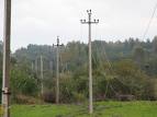
 The main element of rural 10 kV electrical networks is a distribution line, which is recommended to be carried out according to the highway principle.
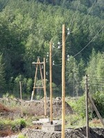
10 / 0.4 kV supporting transformer substations (TSS) are connected to 10 kV trunk lines, through which the mutual redundancy of the lines is realized. Transformer substations are 10 / 0.4 kV transformer substations with developed 10 kV switchgear (to which 10 kV radial lines are connected), intended for automatic separation and redundancy of the main line, placement of automation and telemechanics and (or) distribution points (RP) .
The main section of the newly built or reconstructed 10 kV lines is recommended to be filled with steel-aluminum wire with the same cross-section of at least 70 mm2, which provides the possibility of powering one line in emergency and repair modes loads of the two inter-reserve lines.In these cases, the 10 kV line normally has only one grid backup from an independent power source.
10 kV line disconnectors are installed on the mains of 10 kV overhead lines to limit the length of the line section, including branches, to 3.5 km; on a branch of a 10 kV overhead line, with a length of more than 2.5 km.
The minimum permissible cross-sections of steel-aluminum conductors of 10 kV overhead lines according to the conditions of mechanical strength should be: in areas with a standard thickness of the ice wall up to 10 mm-35 mm2; 15 … 20 — 50 mm2; more than 20 mm — 70 mm2; aluminum wires — 70 mm2.
The minimum permissible cross-section of aluminum conductors of overhead lines of 0.38 kV according to the conditions of mechanical strength should be: in areas with a standard ice wall thickness of 5 mm — 25 mm2; 10 mm or more — 35 mm2; steel-aluminum and aluminum alloy — 25 mm2 in all climatic regions. No more than two or three conductor cross-sections should be provided on overhead lines departing from one 10 / 0.4 kV transformer substation.
 The conductivity of the neutral conductor of 0.38 kV lines supplying mainly (more than 50% in terms of power) single-phase electrical receivers, as well as electrical receivers of livestock and poultry farms, must be at least the conductivity of the phase conductor. In all other cases, the conductivity of the neutral conductor must be taken at least 50% of the conductivity of the phase conductors.
OTPs are installed at consumers of category I, in the yards of households of the central estates of collective and state farms.
The OTP diagram is shown in the figure.It is recommended to build a distribution point (RP) at the nodes of the 10 kV network, if in the future it is planned to build a 35-110 / 10 kV substation here. It is recommended to transfer 10 / 0.4 kV transformer substations to supply from 10 kV OTP (RP) busbars if they are connected to the main section of the line by a branch.
Reinforced concrete supports with increased strength must be used on 0.38 kV overhead lines.
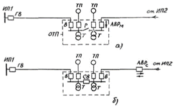
OTP circuit: IP — power supply; GV, SV, V — head, sectioning and switches in the 10 kV line; R — disconnector 10 kV; TP — transformer substation; T — transformer 10 / 0.4 kV; AVR, AVRM — network and local automatic transfer switches.