Lifting electromagnets: device, switching circuit
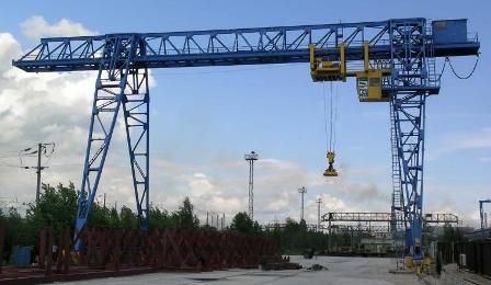
The use of lifting electromagnets allows to reduce the duration of ferromagnetic materials gripping and removal operations during transportation.
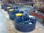
Lifting round electromagnets
Lifting round electromagnets such as Soviet-made M-22, M-42, M-62 (early analogs-M-41, M-61 or newer analogs-M-23, M-43, M-63) are intended for gripping and moving by crane mechanisms of scrap, scrap, blooming, forgings, packaged scrap, rolled products. But they are used successfully when transferring products with long sheets and when working on a traverse. In the USSR, light series (M-22, M-21), medium series (M-42, M-41) and heavy series (M-62, M-61) are produced.
Lifting rectangular electromagnets
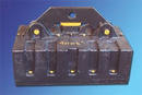 Lifting rectangular electromagnets of the PM-15, PM-25 type of Soviet production (later analogues-PM-16, PM-26) are designed for lifting and moving forgings, sheet metal, blooms. When installed on a traverse, they can carry long loads of up to 25 meters (e.g. rails). They are also used to extract ferromagnetic material (metal inclusions) from bulk cargo transported on conveyor belts (conveyor) with short-term activation of the forced mode by the metal detector.
Lifting electromagnets with heat-resistant insulation
There are also load-lifting electromagnets with heat-resistant insulation, which are designed to grip and move hot loads with temperatures up to 500 ° C. The same magnetic pulleys can carry loads with temperatures up to 700 ° C, but under the condition of reducing PV (by switch-on time) up to 10-30% and with a reduction of the solenoid switch-on time to 1-2 minutes. It should be taken into account that the magnetic properties of the transported load deteriorate significantly when it reaches 750°C.
The lifting electromagnets are designed for periodic abrupt operation with a duty cycle = 50% with a cycle duration of no more than 10 minutes.
The choice of lifting electromagnets is made according to the voltage, the mode of operation, the lifting force, the energy consumption, the shape of the load and its temperature.
The device for lifting electromagnets (for example, an electromagnet round shape, type M-42)
 A coil filled with mixed mass is placed inside the steel body of the lifting electromagnet. Pole shoes are attached to the body with bolts. The coil is protected from below by a ring of non-magnetic material. Current wire to the coil The lifting electromagnet is effected by a flexible cable which is automatically wound on the cable drum when ascending and unwound from it when descending. The lifting electromagnet is suspended from the hook by chains.
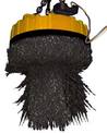
The lifting force of the lifting electromagnet depends on the nature and temperature of the load being lifted: with a high density of the load (plates, blanks), the lifting force increases, with a lower density (scrap, shavings) it significantly decreases. As the temperature increases, the magnetic permeability decreases, reaching zero at 720 ° C, as a result of which the lifting force also decreases. to zero.
The coils of such electromagnets are supplied with direct current, have high inductance and significant residual flux. magnetism… Therefore, when the electromagnet is switched off, measures must be taken to limit surges, as well as to quickly release the electromagnet from the load.
Solenoid lift control circuit
 The lifting electromagnet is usually controlled by a magnetic controller whose equipment panel is placed in a cabinet and installed in the crane operator's cabin.
The figure shows a circuit diagram of the magnetic controller PMS-50, which has: input switch (switch) BB, fuses Pr1 and Pr2, contactor inclusion KB, contactor demagnetization KR, resistors PS and PC.
Direct current to the coil of the electromagnet Em is supplied from a 220 V network or from a converter installed on the tap.
To grip the load with an electromagnet, the handle of the controller is placed in position B. The contact KK of the controller is closed. The KB contactor receives power, which with its contacts connects the EM electromagnet to the power source and the load is picked up.
Electrical schematic diagram of the control of the lifting electromagnet
To release the solenoid from the load, the controller handle is moved to the O position.The contact KK opens, the contactor KB loses its power supply and is disconnected from the source of the EM coil, but the current in it does not disappear immediately, and under the action of the EMF of self-induction, it continues to flow in the same direction in the circuit with resistors PS and PC. In this case, the voltage between points 1 and 2 are sufficient to turn on the contactor KP. As a result, the coil Em turns out to be under a voltage of reverse polarity, the current in it decreases intensively and then increases in the opposite direction to the value necessary to remove the residual magnetism. The electromagnet is released by a load, even a very light one, for example by shavings.
In the process of changing the current of the electromagnet, the voltage on the coil KR decreases, and at a certain value of it, the contactor KP is turned off, which leads to the interruption of the demagnetization circuit, but the coil Em remains closed to resistors. This eliminates unacceptable overvoltages on the electromagnet.