Schemes for connecting asynchronous electric motors to the network
Wiring diagrams for single-speed squirrel-cage induction motors
Squirrel-rotor induction motors up to and including 11 kW have three output ends in the input unit and a ground clamp. The windings of these motors are star or delta connected and are designed to be connected to one of the standard voltages.
Motors from 15 to 400 kW have six terminals in the input device and a ground clamp. These motors can be switched for two voltages: 220/380 or 380/660 V. The winding circuits are shown in the figure.
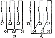
Schemes for switching on a single-speed motor for two voltages 220/380 or 380/660 V: a — star (higher voltage); b — triangle (low voltage).
Wiring diagrams of multi-speed squirrel-cage rotor induction motors
Multi-speed asynchronous motors differ from the stator windings by only one speed and the rotor slots. The number of gears can be two, three or four.For example, the 4A series offers multi-speed motors with the following speed ratios: 3000/1500, 1500/1000, 1500/750, 1000/500, 1000/750, 3000/1500/1000, 3000/1500/750, 1500 /1000/750 , 3000/1500/1000/750, 1500/1000/750/500 rpm.
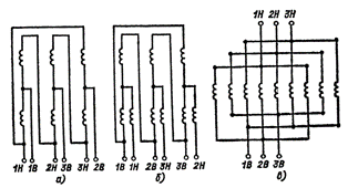
Connection diagrams of windings of two-speed motors: a — D / YY. Low speed — D: 1V, 2V, ZV are free, voltage is applied to 1N, 2N, 3N. The highest speed is YY. 1H, 2H, 3H are closed to each other, the voltage is applied to 1V, 2V, 3V, b — D / YY with an additional winding. Low speed — YY with additional winding, IB, 2B, 3B are shorted together: voltage is applied to 1H, 2H, 3H. High speed — L: W, 2H, 3H are free, voltage is applied to IB, 2B, 3B, is — YYYY. Low speed: 1V, 2V, 3V are free, the voltage is applied to 1H, 2H, 3H. High speed: 1H, 2H, 3H are free, voltage is applied to IB, 2B, 3B.
Two-speed motors have a single pole-changeable six-wire winding. The winding of motors with a speed ratio of 1: 2 is made according to the Dahlander scheme and is connected in a delta (D) at the lowest speed and in a double star (YY) at a higher speed. The coil connection scheme is shown in the figure.
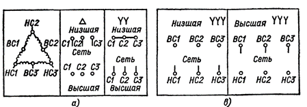
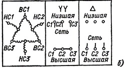
Connection diagram of two-speed motors with a speed ratio of 2: 3 and 3: 4: a — D / YY without an additional winding; b — D / YY with additional winding; in — YYYY / YYYY
The windings of two-speed motors with a speed ratio of 2: 3 and 3: 4 are connected either in a triple star or in a delta — a double star without an additional winding or with an additional winding.
Three-speed motors have two independent windings, one of which is made according to the Dahlander scheme and is connected according to the D / YY scheme. The number of output ends of the three-stage motor is nine.
Four-stage motors have two independent pole-switching windings made according to the Dahlander scheme, with 12 leads. The connection diagram in the input device is shown in the figure. When one of the coils is connected to the network, the second coil remains free.
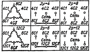
Connection diagram for four-speed motors
