Starting rheostats
In accordance with resistor assignment rheostats are divided into starting, starting, regulating, regulating, charging and excitation.
Starting rheostats and the starting part of the starting rheostat to reduce the size, they must have a large time constant. These rheostats are designed for short-term operation, and the requirements for increased resistance stability are not imposed on them. According to existing standards, the starting rheostat heats up to the maximum temperature after three starts with intervals between starts equal to twice the start time.
All other rheostats are subject to resistance resistance requirements and are designed to operate in long-term mode. In electric drive, the most common rheostats with switchable metal resistors. They are used for switching flat, drum and cam controllers (at high powers).
According to the type of radiator, rheostats can be natural air or oil cooled, forced air, oil or water cooled.
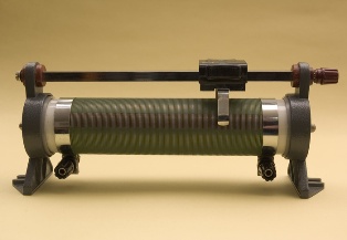
Natural design with air-cooled rheostat
In natural air-cooled rheostats, the switching device and resistors are arranged so that convective air currents moving from the bottom up cool the resistors. The covers covering the rheostat must not obstruct the circulation of the cooling air. The maximum enclosure temperature must not exceed 160 °C. The temperature of the contacts of the switching device must not exceed 110 ° C.
All types of resistors are used in such rheostats. At low power, the resistors and the controller are assembled in one device. At high capacity, the controller is an independent device.
Rheostats of the RP and RZP series are used to start DC motors with shunt and combined excitation with a power of up to 42 kW. These rheostats, in addition to the resistors and the controller, contain an additional contactor used for undervoltage protection and a maximum relay for overcurrent protection.
Resistors are manufactured on porcelain frames or as frame elements. The switching device is made in the form of a flat controller with a self-aligning bridge contact. The controller, the small-sized contactor KM and the maximum instantaneous relay of KA are installed on a common panel. The rheostat blocks are mounted on a steel base. The housing protects the rheostat from water drops, but does not impede the free flow of air.
The electrical circuit for turning on one of these types of rheostats is shown in the figure. When starting the engine, the shunt excitation coil Ш1, Ш2 is connected to the network and a starting resistor is introduced into the armature, the resistance of which decreases with the help of the controller as the engine speed increases.The movable bridge contact 16 closes the fixed contacts 0 — 13 with the current-collecting busbars 14, 15 connected to the winding circuits of the motor.
Switching circuit of the starting rheostat
In position 0 of contact 16, the coil of the contactor KM is short-circuited, the contactor is turned off and the engine is turned off. In position 3, the supply voltage is applied to the coil of the KM, the contactor operates and closes its contacts. In this case, full voltage is applied to the excitation coil and all rheostat start resistors are included in the armature circuit.
In position 13, the starting resistance is fully withdrawn. In position 5 of the movable contact 16, the coil of the contactor KM is energized through the resistor Radd and the closed contact KM. At the same time, the power consumed by the CM decreases and the release voltage increases. In the event of a voltage drop of 20 — 25% below the nominal contactor KM drops and disconnects the motor from the network, protecting against an unacceptable drop in motor voltage.
In the event of an overcurrent of motor overload (1.5 — 3) Aznom, the maximum relay of KA is activated, which breaks the circuit of the coil KM. In this case, the KM contactor turns off and disables the motor. After turning off the motor, the KA contacts will close again, but the KM contactor will not turn on, because after turning off the KM, the circuit of its coil remains open. To restart it is necessary to put contact 16 of the controller in position 0 or at least in the second position.
To switch off the motor, contact 16 is set to 0. When the mains voltage drops to the release voltage of the contactor, its armature disappears and the motor is disconnected from the mains.In this way, minimum engine protection is achieved. Pins 1, 2, 4, 5 are not used which prevents the controller from arcing between high current pins. The described scheme provides remote shutdown of the motor using the Stop button with NC contact.
About choosing a starting rheostat, I need to know power of an electric motor, the starting conditions and the nature of the load change during starting, as does the motor supply voltage.
Oil rheostats
In oil rheostats, the metal elements of the resistors and the controller are located in the transformer oil, which has significantly higher thermal conductivity and heat capacity than air. This allows the oil to transfer heat more efficiently from the heated metal parts. Due to the large amount of oil involved in the heating, the heating time of the rheostat increases sharply, which makes it possible to create starting rheostats with small dimensions for high load power.
To prevent local overheating in resistors and to improve their thermal contact with oil, resistors in the form of a free spiral, wire and strip fields zigzag from electrical steel and cast iron are used in rheostats.
At temperatures below 0 ° C, the cooling ability of the oil sharply deteriorates due to an increase in its viscosity. Therefore, oil rheostats are not used at negative ambient temperatures. The cooling surface of the oil rheostat is determined by the generally cylindrical surface of the housing.This surface is smaller than the cooling surface of the resistors wire; therefore, the use of oil rheostats in long-term mode is impractical. The low allowable heating temperature of the oil also limits the power that the rheostat can dissipate.
After starting the motor three times, the starting rheostat must cool down to ambient temperature. Since this process takes about 1 hour, oil starting rheostats are used for infrequent starts.
The presence of oil dramatically reduces the coefficient of friction between the contacts of the switching controller. This reduces wear on the contacts and the torque required on the control handle.
The low frictional forces allow to increase the contact pressure by 3-4 times increasing the current load of the contacts. This makes it possible to drastically reduce the size of the switching device and the entire rheostat as a whole. In addition, the presence of oil improves the conditions for extinguishing the arc between the contacts of the switching device. However, the oil also plays a negative role in the operation of the contacts. Oil breakdown products, settling on the contact surface, increase transition resistance and therefore the temperature of the contacts themselves. As a result, the oil decomposition process will be more intensive.
The contacts are designed so that their temperature does not exceed 125 ° C. Oil decomposition products are deposited on the surface of the resistors, worsening the thermal contact of the wires with the oil. Therefore, the maximum permissible temperature of the transformer oil does not exceed 115 ° C.
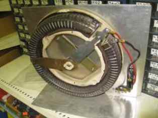
Oil rheostats are widely used for three-phase starting asynchronous rotor motors… For motor powers up to 50 kW, flat controllers with circular movement of the movable contact are used. At high powers, a drum controller is used.
Rheostats can have blocking contacts to signal the state of the device and block with contactor in the motor stator winding circuit. If the maximum resistance of the rheostat is not yet engaged, the closing contactor winding is open and no voltage is supplied to the stator winding.
At the end of starting the electric motor, the rheostat should be fully pulled out, and the rotor should be short-circuited, since the elements are designed for short-term operation. The greater the power of the motor, the longer the acceleration time and the greater the number of stages the rheostat must have.
To select a rheostat, you need to know the rated power of the motor, the locked rotor voltage at the rated stator voltage, the rated rotor current and the load level of the motor at start-up. According to these parameters, you can choose the starting rheostat using the reference books.
Disadvantages of the oil rheostat low permissible starting frequency due to slow cooling of the oil, contamination of the room from splashes and oil vapors, the possibility of oil ignition.