How to measure stray currents in a cable line to protect the cable from corrosion
To define corrosive hazard and the development of cable line protection measures constitute a potential diagram of the cable network, which is periodically adjusted. For this purpose, a set of tests is carried out on cable lines, including the following measurements:
a) the potential difference between the cable sheaths and ground,
b) the strength and direction of the current flowing through the sheath of the cable,
(c) the current density flowing from the cable to the ground.
Experience shows that potentials of 0.1 — 0.2 V are sufficient to create conditions for active breakdown of the lead coating. To measure potentials, you need to use high resistance voltmeters, about 10,000 ohms per 1 V.
A universal corrosion measuring device is used to measure the leakage currents. According to the measurement data, the average values of potentials and currents are determined. A dangerous value of the current density is 0.15 mA / dm2 or more.
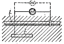
 Scheme for measuring the potentials on the sheaths of the cables and the density of the stray currents flowing from them: 1 - cable; 2 — electrode.
When measuring the potentials of cable sheaths with respect to earth, in order to avoid errors arising from the possibility of galvanic couples, the earth electrode is made of the same metal as cable sheath (lead, aluminum) on which the stray currents are measured. A simple piece of cable with a length of 300 - 500 mm.
When measuring current density, instead of a millivoltmeter, turn on a milliammeter. By measuring the total current flowing from the electrode to the ground Azze and knowing the size of the surface of the electrode S, determine the specific density of the current flowing into the ground, Azudari: Azud = Azze / C

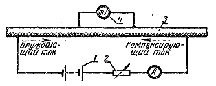
Scheme for measuring stray currents flowing along the lead sheath: 1 — auxiliary battery; 2 — rheostat; 3 — cable; 4 — indicator device.
By current flowing along the sheath of the cable Azck, it is desirable to measure it by the compensation method. From an external source, the reverse current flows through the cable sheath, which compensates for stray current flowing along the sheath. At the moment of full compensation, the millivoltmeter reading is zero, and the current passing from an external source Azn is equal to the forward current flowing along the sheath of the cable Azck = AzNS.
The existing technical operation rules prescribe that the leakage currents must be measured at least twice during the first year of operation. cable line… The frequency of measurements in subsequent years is established based on the results of the first measurements and the analysis of the corrosion zones.
