Methods of accelerating and decelerating the operation of electromagnets and electromagnetic mechanisms
For electromagnets whose response time must differ from the normal (0.05 — 0.15 s.) In one direction or another, special measures are needed to guarantee the time parameters. These measures can be aimed either at changing the design and parameters electromagnetor about using chain methods to change response times. In this regard, these methods are called constructive or chain methods.
Constructive methods to reduce reaction time
Solenoid start time. To reduce startup time in a constructive way, they decrease eddy currents in the magnetic circuit electromagnets, which increase the start-up time, because they dampen the magnetic flux when it changes. For this purpose, the magnetic circuit of the Electromagnet is made of magnetic materials with high electrical resistance. In the massive parts of the magnetic circuit, special slots are made that cross the paths of eddy currents.The magnetic core is made of sheets of electrical steel.
The time of movement of the electromagnet. To reduce running time, they seek to reduce armature travel, reduce armature mass and associated moving parts. Reduce friction in axles or between moving and stationary structural parts. Armature rotation is applied to the prism, not the axes.
Schematic methods for reducing the response time of an electromagnet. In cases where the design methods are ineffective or inapplicable, schemes are used to change the time parameters of electromagnets. Schematic methods only affect the starting time of the electromagnet through its parameters.
The start-up time of the electromagnet during actuation can be reduced if, simultaneously with the increase in the supply voltage of the electromagnet, an additional resistance Rd is introduced into the coil circuit of such a value that the value of the steady-state current in the electromagnet coil does not change at the same time , these.
Picture 1.
The reduction in starting time is obtained here due to
The disadvantage of this circuit is that the effect is achieved due to a proportional increase in the power lost in the additional resistance.
Figure 2.
In the diagram of fig. 2 an additional resistor is connected in series with the coil of the electromagnet, shunted capacitor… The supply voltage in this circuit also increases. However, the additional resistor is selected in the same way as in the circuit of Fig. 1.The forcing of the actuation process here occurs due to the fact that at the first moment after the application of the voltage, the uncharged capacitance C creates an additional path for the current. Therefore, due to the charging current of the capacitor in the coil of the electromagnet, the current grows faster. Transient process, before starting in this case the anchors are described by the following equations:
For the circuit under consideration, there is a value of the optimal capacity at which the response time is minimal
The disadvantage of this scheme is the presence of a capacitor, the capacity of which is usually significant.
 In fig. 3 shows a circuit forcing operation in which an additional resistance is connected in series with the coil of the electromagnet interrupted by an opening contact. This contact is connected to an armature. When the coil is turned off, it closes, opening only at the end of the armature stroke. During the period of operation, a transient current flows through the coil, the steady-state value of which would be equal to. But due to the fact that the armature is attracted, there is an opening of the contact K, shunting Rd, and the current rises to a lower steady-state value equal to U / (R + Rd), which should be enough to hold the armature of the electromagnet in the attracted position. This scheme can also be used to reduce the size of the electromagnet in those installations where it is particularly important to obtain their minimum weight.
Figure 3.
The disadvantage of the circuit is the presence of an NC contact.
Methods of increasing the response time of electromagnetic mechanisms
To increase the response time of the solenoids, all common factors are used, resulting in an increase in both starting time and driving time. These methods can include both constructive and chaining methods.
Of the construction methods leading to an increase in the movement time, such factors as increasing the stroke of the anchor, increasing the weight of moving parts, mechanical and electromagnetic shock absorbers are used. The latter have found application in relays that create long time delays, for example time relays.
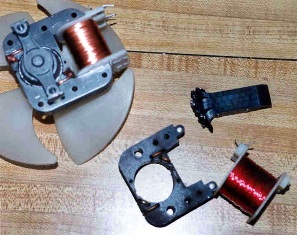
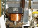
Figure 4
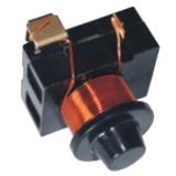 In the case of electromagnetic damping, short-circuited windings in the form of copper (aluminum) sleeves are used, mounted on the core of the magnetic circuit (Fig. 4). The eddy currents that occur in these bushings when the main coil of the electromagnet is closed or opened slow the change in magnetic flux and create a delay in operation, both when the armature is attracted and when the armature is released. In the second case, a greater retarding effect is achieved, since when the winding is turned off, the transient occurs when the armature is pulled, when inductance the system is large. Therefore, the armature release delay in electromagnets with shorted bushings can be longer than in pull-out.
Electromagnets with an electromagnetic valve can provide a release time delay of up to 8-10 s.
To change the response time of electromagnets by circuit methods, the most common schemes are the following.
In those cases where the supply voltage is fixed, the turn-on start time can be increased by connecting an additional resistance Rd in series with the solenoid coil. The increase in pick-off time occurs here due to a decrease in the steady-state value of the current in the circuit. Instead of a resistor, you can also include an inductance, which increases the time constant of the circuit without changing the steady-state current.
To increase the start-up time of electromagnetic mechanisms during shutdown, the circuits shown in Fig. 5. a B C)
Figure 5.
An increase in the start-up time of the electromagnetic mechanisms in these circuits occurs due to the fact that after opening the circuit in the circuits (R, L-Rsh), (R, L-VD) (Fig. 5 a, b), the EMF arising in the coil ... self-induction creates a current that inhibits the decay of the magnetic flux in the electromagnet. The start-up delay is determined by the decay time of the current in the circuits, which depends on the parameters of those circuits.
In the circuit of fig. 5, the delay in starting the electromagnet on release occurs due to the fact that after opening the circuit, the charged capacitance C is discharged in the circuit (C, Rx-R, L) and the discharge current slows down the decay of the flux in the electromagnet.