Transformer substations for voltage 6 — 10 / 0.38 kV in distribution networks
Transformer substations 6 … 10 / 0.38 kV, which are often called consumer substations, are designed to supply distribution lines with a voltage of 0.38 kV, in most cases three-phase four-wire with a grounded neutral.
In distribution networks, both single-transformer and double-transformer substations with a capacity of 25 to 630 kV-A are used in most cases for outdoor installation. With special justification, closed transformer substations (ZTP) can be installed. Currently, in most cases, networks are designed with complete transformer substations for external installation, although for users of the first category in terms of power supply reliability, ZTPs are increasingly used. External transformer substations are also operational.
The main diagrams of the primary connections of the 10 kV switchgear of the entire transformer substation (KTP) are shown in Figure 1 (some diagrams do not show additional disconnectors that can be installed on the end supports to connect the KTP to the lines). A complete dead-end transformer substation with one transformer (Fig. 1, a) is widely used to supply agricultural consumers.
Figure 1. Main electrical diagrams of switchgear RU 10 kV transformer substations 10 / 0.38 kV
The disconnector, as a rule, is installed on the end support of the 10 kV line, and the 10 kV fuses are installed in the KTP. In case of justification, a load switch can be used instead of a disconnector in the transformer circuit. Scheme b also with one transformer and busbars with load breakers can be used in 10 kV networks, not only with one-way but also with two-way supply, when according to reliability conditions, manual switching after an emergency situation is allowed. The transformer is connected to the busbars through a disconnector and fuses.
 When the load breakers are closed, power can be supplied from a single source with the current passing through bus at a substation… In this scheme it is permissible to replace one of the load break switches with a disconnector with suitable interlocks.
Scheme e combines a single transformer substation with an automatic split point or automatic transfer switch (ATS) on a 10 kV line.The scheme is used in networks with a voltage of 10 kV with one-way and two-way power supply, in which, according to the conditions of power supply reliability, automatic and manual separation of 10 kV lines is required.
Scheme d - a switchgear with two transformers and 10 kV busbars separated by a load switch and a disconnector is mainly used in 10 kV networks with double-sided feeding, where manual separation of 10 kV lines is allowed.
The main mode of operation of the substation is the supply of each transformer from an independent source through the 10 kV line (the sectional load switch is switched off). When the sectional load switch is on, it is possible to supply it from a single source with the current transiting through the transformer substation busbars. Instead of a sectional load switch, an oil switch can be installed (by replacing the load switch with a disconnector on its left country, diagram d). Such a circuit (single circuit breaker bridge circuit) combines a two-transformer substation with an automatic disconnection point or ATS point for a 10 kV line.
Figure 2 shows the main connection scheme of the UZTP 10 / 0.38 kV, developed for the supply of responsible agricultural users, where it is necessary to provide ATS on the 10 kV side. Two-transformer substation, with a capacity of 2x400 kV-A, with a 10 kV switchgear of the nodal type according to the scheme with a split bus system, with four outgoing 10 kV overhead lines and using distribution cells, with circuit breakers of the VK-10 type, using KTP is built back-end type (Fig. 2, a).
Figure 2. The main connection scheme of the UZTP 10 / 0.38 kV substation
The schematic circuit diagram of a complete transformer substation 10 / 0.38 kV with a capacity of 25 ... 160 kV-A is shown in Figure 3.
Figure 3. Connection diagram of KTP-25 ... 160/10
The 10 kV switchgear (RU) consists of a disconnector ВС with earthing knives mounted on the nearest support of the 10 kV line, valve restrictors FV1 … FV3 for the protection of equipment from atmospheric and switching overvoltages on the 10 kV side and fuses F1 … F3 installed in the high-voltage water device, providing transformer protection against multi-phase short circuits. The fuses are connected to the bushings and the power transformer respectively. The rest of the equipment is located in the lower compartment (cabinet), that is, the 0.38 kV switchgear.
Switch S, valve limiters FV4 … FV6 for overvoltage protection on the 0.38 kV side, current transformers TA1 … TAZ, feeding the PI active energy meter and transformers TA4, TA5, connected with thermal relay KK, which provides protection of the power transformer from overload. Switch-on, switch-off and protection of 0.38 kV output lines against short circuit and overload is carried out by automatic switches QF1 … QF3 with combined releases. At the same time, in order to protect the lines from single-phase short circuits in the neutral conductors of the overhead line N1 ... 3, current relays KA1 ... KA3 are installed, which, when activated, close the circuit of the shunt release coil. The relays are configured to operate on single-phase short circuits. in the most remote points of the network.The street lighting line is protected against short circuit with fuses F4 … F6.
When the power transformer is overloaded, the breaking contacts of the thermal relay KK, which in normal mode bypass the coil of the intermediate relay KL, open, supplying it with voltage through resistors R4 and R5. As a result of the operation of the relay KL, lines 1 and 3 are turned off and the resistor R4 is disabled, increasing the resistance in the circuit of the coil of the relay KL. This is necessary to limit to the nominal value (220 V) the voltage supplied to the coil of the relay KL after pulling the armature, which is associated with an increase in the resistance of the relay coil. The overload protection switches off after no more than 1.3 hours at a current 1.45 times the rated current of the power transformer.
Line No2 and street lighting are not interrupted by overload protection. Automatic switching on and off of the street lighting line is carried out by the KS photo relay, and with manual control of this line they use the SA2 switch. The photo relay and switch SA2 act on the coil of the magnetic starter KM.
To maintain a normal temperature near the active energy meter PI in winter conditions, resistors R1 ... R3 are used, switched on through switch SA1.
To control the presence of voltage and lighting of the 0.38 kV switchgear, an EL lamp is used, which is turned on by the switch SA3. The voltage is measured with a portable voltmeter, which is connected to the plug X located in the 0.38 switchgear kV. The SA3 switch allows you to measure the voltage of all phases.
In order to prevent the breaker from tripping under load, an interlock is provided which works as follows. When the closing panel of the 0.38 kV switchgear is opened, the closing contacts of the blocking switch SQ, bypassing the coil of the intermediate relay KL, open and the relay KL is activated, turning off the automatic switches of lines No. 1 and 3. At the same time, the voltage removed from the coil of the magnetic starter KM and the street light line is disconnected.
In this case, the opening contacts of the SQ interlock switch open and open the circuit breaker on line No. 2 (the position of the SQ switch contacts in Figure 3 shown with an open panel covering the 0.38 kV switchgear). Mechanical interlocks are also provided to prevent the HV input device door from opening when the disconnector earthing blades are disconnected, and to disconnect the disconnector earthing blades when the 10kV input device door is open. The door lock of the 10 kV input device and the drive lock of the earthing knives have the same secret. There is one key for them. When the disconnector is engaged, the key cannot be removed from the drive blade. After the power is turned off and the earthing blades of the disconnector are turned on, the key is freely removed from the earthing blade drive and can be used to open the door of the 10 kV input device.
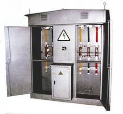
To supply mainly high-power industrial users, the KTP 10 / 0.38 kV series is also used with one and two transformers of the through-type KTPP and dead-end type KTPT with a capacity of 250 ... 630 and 2 ( 250 ... 630) kV-A with external mounting air inlets.Structurally, the single-transformer KTPP and KTPT are made in the form of a single block, in which the 10 and 0.38 kV RUs, as well as a power transformer, are located in the respective compartments. The housing body (cabinet) is made of sheet metal and has doors for servicing 10 kV and 0.38 kV switchgear. Locks are provided for safe operation.
Figure 4. General view of the transformer substation on the mast 10 / 0.38 kV: 1 — arrester, 2 — fuse, 3 — transformer, 4 — service platform, 5 — switchgear cabinet 0.38 kV, 6 — line terminals 0 ,38 kV, 7 — stairs.
Figure 5. General view of a 10 kV disconnection point: 1 — support, 2 — disconnector, 3 — disconnector
A two-transformer KTP consists of two single-transformer blocks connected to each other. RU 10 kV KTPP and KTPP are implemented according to schemes a, b and d (Fig. 1). In particular, a 10 kV switchgear KTPP with a capacity of 250 ... 630 kV-A with one transformer is made according to scheme b (Fig. 1). The layout of the 0.38 kV switchgear is essentially the same as in the figure. 3, however, an option is also provided with the installation of fuses with circuit breakers instead of circuit breakers on outgoing lines, the number of which is increased to four. Mast substations with a capacity of 25 ... 100 kV-A are mounted on a U-shaped support, and 160 ... 250 kV-A - on an AP-shaped support. In most cases, the substations are deadlocked. Image 4 shows a general view of the 10 / 0.38 kV mast transformer substation. All equipment is placed on a U-shaped support.
Transformer 3 is installed on a fenced area 4 at a height of 3 ... 3.5 m. The voltage is supplied to the transformer through a linear disconnection point and fuses 2.The linear trip point includes an actuated disconnector mounted on the end support. The 0.38 kV switchgear is a splash-proof metal cabinet 5 with internal equipment. The entrance to the cabinet from the transformer and the exits 6 to the 380/220 V lines are made in pipes. A folding metal ladder 7 serves to climb to the platform 4, which (folded), like the doors of the cabinet and the drive of the disconnector, is locked with a lock. To protect the transformer substation from overvoltage, valves 1 are installed.