Electrical devices for monitoring loads, forces and moments in metal cutting machines
During the operation of automated equipment, it becomes necessary to control the load, that is, the efforts and moments acting in the elements of machines and machines. This prevents damage to individual parts or unacceptable overloading of electric motors, allows you to choose the optimal mode of operation of machines, make a statistical analysis of operating conditions, etc.
Mechanical load control devices
Very often load control devices are based on a mechanical principle. An elastic element is included in the kinematic chain of the machine, the deformation of which is proportional to the applied load. Exceeding a certain load level triggers a microswitch connected to the elastic element via a kinematic link. Load control devices with cam, ball or roller couplings are widely used in the machine tool industry.They are used in clamping devices, wrenches and other cases where the electric drive operates on a hard stop.
Electrical load control devices
The presence of a sensitive elastic element in the kinematic chain reduces the overall stiffness of the electromechanical drive and worsens its dynamic characteristics. Therefore, they try to obtain information about the magnitude of the load (in this case, the torque) through electrical methods by controlling the current, power, slip, phase angle, etc. consumed by the drive motor.
In fig. 1 and shows a circuit for monitoring the current load on the stator of the induction motor. Voltage proportional to current I the stator of the electric motor, removed from the secondary winding of the current transformer TA, rectified and fed to a low-current electromagnetic relay K, the set value of which is adjusted by potentiometer R2. A low-resistance resistor R1 is required to bypass the secondary winding of the transformer, which must operate in short-circuit mode.
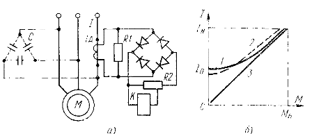
Figure 1. Scheme for monitoring the load of the electric motor by stator current
To control the stator current, fast-acting protective current relays described in ch. 7. The stator current is related to the shaft torque of the motor shaft by a nonlinear shape dependence
where Azn — rated current of the stator, Mn — rated torque, βo =AzO/Azn-multiplicity of the idle current.
This dependence is graphically shown in Fig. 1, b (curve 1). The graph shows that at low loads the stator current of the electric motor changes very slightly and it is impossible to adjust the load in this area.In addition, the stator current depends not only on the torque, but also on the mains voltage. When the mains voltage decreases, dependence 1(M) changes (curve 2), which introduces an error in the operation of the circuit.
The stator current of an electric motor is the geometric sum of the no-load current and the reduced rotor current:
When the load changes, the current changes I2 ' The no-load current is practically independent of the load. Therefore, to increase the sensitivity of small load control devices, it is necessary to compensate for the no-load current, which is mostly inductive.
In low-power electric motors, capacitor group C is included in the stator circuit (dotted lines in Fig. 1, a), which generates a leading current. As a result, the electric motor consumes from the network a current equal to the reduced rotor current, and the dependence 1 (M) becomes almost linear (curve 3 in Fig. 1, b). One disadvantage of this method is the stronger dependence of the load characteristics on fluctuations in the network voltage.
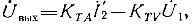
In electric motors with higher power, the capacitor bank becomes bulky and expensive. In this case, it is more expedient to compensate for the no-load current in the secondary circuit of the current transformer (Fig. 2).
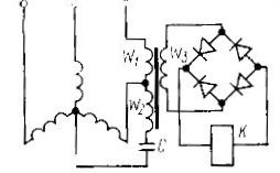
Figure 2. Load control relay with no-load current compensation
The circuit uses a transformer that has two primary windings: current W1 and voltage W2. A capacitor C is included in the voltage winding circuit, which shifts the phase of the current by 90° to the wire.The parameters of the transformer are chosen so that the magnetizing force of the winding W2 compensates that component of the magnetizing force of the winding W1 which is related to the no-load current of the electric motor. As a result, the voltage at the output of the secondary winding W3 is proportional to the rotor current and load torque. This voltage is rectified and applied to the electromagnetic relay K.

In machine control systems, highly sensitive load relays are used, which have a pronounced relay dependence of the output voltage on the torque of the load (Fig. 3, b). The circuit of such a relay (Fig. 3, a) has a current transformer TA and a voltage transformer TV, the output voltage of which is turned on in opposite directions.
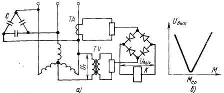
Figure 3. High sensitivity load control relay
If the no-load current is compensated for example by capacitor bank C, the output voltage of the circuit is
where Kta, Ktv- conversion factors of current and voltage transformers, U1 — voltage in the motor phase.
By changing Kta or Ktv, it is possible to configure the circuit so that for a given torque Mav the output voltage is minimum. Then any deviation of the mode from the given one will cause a sharp change U out and trigger relay K.
Similar schemes are used to control the moment of contact of the grinding disc with the workpiece during the transition from the rapid approach of the grinding head to the working feed.
Load relays, based on the control of the power consumed by the asynchronous electric motor from the network, work more precisely. Such relays have a linear characteristic that does not change with fluctuations in the mains voltage.
The voltage proportional to the power consumption is obtained by multiplying the voltage and current of the stator of the induction motor. For this, load relays based on non-linear elements with quadratic volt-ampere characteristic-quadrators are used. The principle of operation of such relays is based on the identity (a + b)2 — (a — b)2 = 4ab.
The load relay is shown in fig. 4.
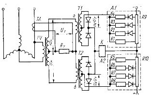 Figure 4. Power consumption relay
The current transformer TA loaded on the resistor RT and the voltage transformer TV forms on the secondary windings voltages proportional to the current and phase voltage of the electric motor. The voltage transformer has two secondary windings on which equal voltages -Un and +Un are formed, phase shifted by 180 °.
The sum and difference of the voltages are rectified by a phase-sensitive circuit consisting of matching transformers T1 and T2 and a diode bridge, and are fed to the squarers A1 and A2 made according to the principle of linear approximation.
The squarers contain resistors R1 — R4 and R5 — R8 and valves locked by the reference voltage taken from dividers R9, R10. As the input voltage increases, the valves open in turn and new resistors connected in parallel with resistors R1 or R5 are put into action. As a result, the current-voltage characteristic of the quadrilateral has the shape of a parabola, which ensures the quadratic dependence of the current on the input voltage. The output electromechanical relay K is related to the difference between the currents of the two squares, and in accordance with the basic identity, the current in its coil is proportional to the power consumed by the electric motor from the grid.With the correct setting of the quadrants, the power relay has an error of less than 2%.
A special class is formed by pulse-time pulse relays with double modulation, which are becoming more and more common. In such relays, a voltage proportional to the motor current is fed to a pulse width modulator, which generates pulses whose duration is proportional to the measured current: τ = K1Az ... These pulses are fed to an amplitude modulator controlled by the mains voltage.

As a result, the amplitude of the pulses turns out to be proportional to the voltage on the stator of the electric motor: Um = K2U. The average value of the voltage after double modulation is proportional to the current and voltage induction: Ucf = fK1К2TU, where f is the modulation frequency. Such power relays have an error of no more than 1.5%.
A change in the mechanical load on the induction motor shaft leads to a change in the phase of the stator current relative to the mains voltage. As the load increases, the phase angle decreases. This allows you to build a load relay based on the phase method. In most cases, relays respond to the cosine or phase angle factor. By their characteristics, such relays are close to power relays, but their design is much simpler.
If we exclude the quadrants A1 and A2 from the circuit (see Fig. 4) and the corresponding transformers T1 and T2 in it, replace with resistors, then the voltage between points a and b will be proportional to cosfi, which also changes depending on the motor load . The electromechanical relay K, connected at points a and b of the circuit, allows you to control a given level of load on the electric motor.The disadvantage of circuit simplification is the increased error associated with a change in line voltage.