Engine speed control devices
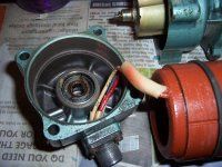
Asynchronous electric motors are widely used in countercurrent brake circuits. induction speed control relay... The input shaft of the relay 5, on which a cylindrical permanent magnet 4 is mounted, is connected to the shaft of the electric motor, the angular speed of which is to be controlled.
When the electric motor rotates, the magnetic field crosses the wires of the short circuit 3 of the rotary stator 6. An EMF is induced in the winding, the value of which is proportional to the angular speed of rotation of the shaft. Under its influence, a current appears in the coil and an interaction force arises, which tends to rotate the stator 6 in the direction of rotation of the magnet.
At a certain rotational speed, the force increases so much that limiter 2, overcoming the resistance of the flat spring, switches the relay contacts. The relay is equipped with two contact nodes: 1 and 7, which are switched depending on the direction of rotation.
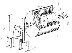
Figure 1. Inductive speed control relay
An induction speed control relay has a rather complex design and low accuracy that can only be acceptable for coarse control systems. Higher speed regulation accuracy can be achieved by using a tachogenerator — a measuring micro machine, the voltage at the terminals of which is directly proportional to the speed of rotation.
Tacho generators are used in variable speed drive feedback systems with a wide rpm range and therefore have an error of only a few percent. The most common are DC tachogenerators.
In fig. 2 shows a diagram of a speed control relay for an electric motor M using a tachogenerator G, the armature circuit of which includes an electromagnetic relay K and a regulating rheostat R. When the voltage at the armature terminals of the tachogenerator exceeds the operating voltage, the relay is turned on in the external circuit.
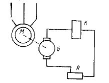
Figure 2. Speed control relay with tachogenerator
 Figure 3. Schematic of a tachometer bridge
As the resistance of the armature circuit increases, the accuracy of the circuit increases. Therefore, sometimes the relay is connected to the tachogenerator through an intermediate semiconductor amplifier. It is also possible to use semiconductor non-contact threshold elements with a stable response voltage for this purpose.
The reliability of the circuit can be improved if the DC tachogenerator is replaced by a contactless asynchronous tachogenerator.
An asynchronous tachogenerator has a hollow non-magnetic rotor made in the form of glass. The stator has two windings at an angle of 90 ° to each other. One of the coils is connected to an alternating current network.A sinusoidal voltage is removed from the other winding, which is proportional to the speed of the rotor. The frequency of the output voltage is always equal to the frequency of the mains.
 In modern DC Executive motors, the tachogenerator is built into the same housing as the machine and is mounted on the same shaft as the main motor. This reduces output voltage ripple and improves the accuracy of speed regulation.
PT-1 type DC tachogenerators with electromagnetic excitation are commonly used in PBST series electric motors. High torque DC motors I have a built in permanent magnet excited tacho.
In cases where the DC motor M does not have a tachogenerator, its speed can be controlled by measuring the armature EMF. For this, a tachometric bridge circuit is used, which is formed by two resistors: R1 and R2, armature Ri and additional poles of the machine Rdp. Output voltage of tachometer bridge Uout = U1 — Udp, or
Uout = (Rdp / Rdp + Ri) x E = (Rdp / Rdp + Ri) x cω
The last equality is valid under the condition that the magnetic flux of the electric motor is constant. Including a threshold element at the output of the tachometric bridge, a relay is obtained that is set to a certain angular speed of rotation. The accuracy of the tachometer bridge is low due to the variability of the brush contact resistance and the heating imbalance of the resistance.
If the DC motor is operating on an artificial characteristic and a large additional resistance is included in the armature, the speed relay function can be performed by a voltage relay connected to the armature terminals.
Voltage in the armature of the electric motor Uja = E + IjaRja.
Since I = (U — E) / (Ri + Rext), we get Ui = (Rext / (Ri + Rext)) x E + (RI / (Ri + Rext)) x U, then the second term can be neglected and the armature terminal voltage can be considered directly proportional to the emf and the speed of rotation of the motor.
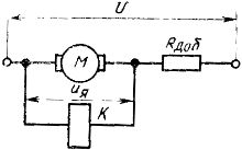
Figure 4. Speed control with voltage relays
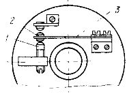 Figure 5. Centrifugal speed control relay
They have a very simple design. centrifugal speed switches... The basis of the relay is a plastic face plate 4, mounted on a shaft, the speed of rotation of which must be controlled. A flat spring 3 with a massive movable contact 2 and a fixed adjustable contact 1 are fixed on the front plate. The spring is made of special steel, the modulus of elasticity of which is practically independent of temperature changes.
When the face plate rotates, a centrifugal force acts on the movable contact, which at a certain speed of rotation overcomes the resistance of the flat spring and switches the contacts. Current is supplied to the contact device through slip rings and brushes, not shown in the figure. Such relays are used in speed stabilization systems for DC micromotors. Despite its simplicity, the system maintains speed with an error on the order of 2%.