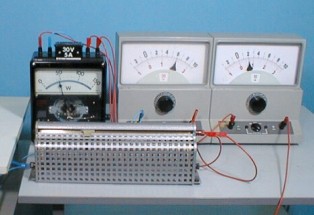
How to properly connect a wattmeter to a DC circuit
It has a wattmeter for a rated current of 5 A and a rated voltage of 300 V. How to connect it to the mains?
If the load current Azx is less than the permissible current, that is, in this case less than 5 A, and if the voltage in the measuring circuit is less than the permissible voltage of the coil, that is, less than 300 V, then the switching circuit has the following form (Fig. 1, a): first turn on the series coil of the wattmeter — collect the current circuit (shown in the figure with a bold line), then collect the voltage circuit, for this the beginning of the voltage coil of the wattmeter is connected to jumper K to the start of the current coil connected to one of the grid terminals, and the end of the voltage coil connected to another grid terminal.
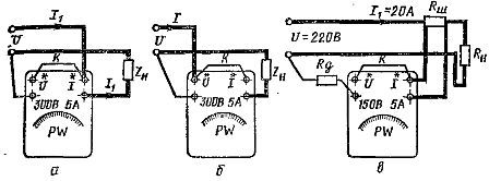
Figure 1. Schemes for connecting a wattmeter: a — directly in the network correctly, b — incorrectly, c — in a network with high voltage and high current.
Sometimes when a circuit is turned on in it include resistance jumpers (Fig. 1, b).This cannot be done, since in this case an operating current passes through the jumper, and not a small current of the voltage circuit, as in the scheme discussed earlier. In addition, in the current circuit of the wattmeter coil, which has a low resistance, the resistance of the jumper itself and two resistances of contact transitions are added. All this leads to the appearance of an additional error in the measurement of power.
If the scale of the device is not calibrated in power units (for example, in a multi-limit electrodynamic wattmeter), but has a certain number of divisions N, then to measure power at this measurement limit, the value of the division of the wattmeter must be determined by the formula:
SN = AznUn/ H,
where Un — nominal voltage of the wattmeter or limit of voltage measurement, Azn — current of wattmeter or limit of current measurement, A, N — number of divisions of the wattmeter scale (usually 100 or 150).
Let a wattmeter be given with Un = 150 V, Аzn = 5 A and n= 150. Then the division cost of the device Cn = 150 x 5/150 = 5 W / div,
To determine the power according to the readings of the device, you need the reading of the device in divisions of scales n multiply by the cost per division Cn:
P = nSn.
If the mains voltage is greater than the allowable voltage of the voltage coil and the current is greater than the allowable current of the current coil, then it is necessary constant current circuit to connect the device, use an additional resistor and measuring shunt (Fig. 1, c).
How to calculate the resistance of an additional resistor and shunt for connecting a wattmeter to a DC circuit
The value of the shunt resistance for connecting the wattmeter for the circuit shown in Figure 1, c, can be determined by the formula:
rw = ra (p — 1) = ra (Ia / In — 1),
where ra — resistance of the current winding of the wattmeter, Ohm, p The shunting coefficient is and the value of the resistance of the additional resistor is from the expression rd = rv (q — 1) = rv (U / Un — 1),
where rv is the resistance of the wattmeter's voltage coil, ohms.
For example, for a wattmeter with a nominal voltage of the voltage coil Un = 150 V and a nominal current of the current coil Azn = 5 A, included in the measuring circuit with a voltage of 220 V (Fig. 1, c) at a current of about 20 A, it is necessary to the resistances of the additional resistor and the shunt are calculated.
Shunt resistance value rw = ρα /(20/5-1) = ρα /3,
then a shunt whose resistance is three times less than the resistance of the current circuit of the wattmeter is required to connect the wattmeter. The resistance of the additional resistor ra = rv (220/150—1) =0.46 rv,
Actual power value P = Pwpq, where Pw is the wattmeter reading if its scale is calibrated in power units.
If the wattmeter is shunt connected, then the separation value can be determined as follows:
C'n = (UnAzn / pq) = Cn x p x q
In the example given, p = 4 and q = 1.46, therefore the wattmeter reading must be multiplied by 5.86 to determine the actual power value, which is inconvenient. Therefore, when choosing a shunt and an additional resistor, they tend to take the coefficients q and p equal to integers.
In this example it is convenient to take p = 5 and q = 2, i.e.rw = ра / 4 and Rd=rv, then the measured power value can be determined by multiplying the readings of the device by 10. The new wattmeter division value will be equal to C'n= 150x 2 x 5 x 5/150 = 50 W / part.,
where 150 x 2 = 300 V is the new wattmeter voltage measurement limit, 5 x 5 = 25 A is the wattmeter's new current measurement limit.
An external additional resistor should be included only after the voltage winding of the wattmeter, and not in front of it, otherwise the potential of the moving coil with respect to the stationary one may reach values dangerous for insulation.