Starting and regulating rheostats: switching circuits
A rheostat is called an apparatus consisting of a set of resistors and a device with which you can adjust the resistance of the included resistors and thus regulate alternating and direct current and voltage.
Differentiate between air-cooled and liquid-cooled (oil or water) rheostats… Air cooling can be used for all rheostat designs. Oil and water cooling is used for metal rheostats, the resistors can either be immersed in the liquid or flow around it. It should be borne in mind that the coolant must and can be cooled with both air and liquid.
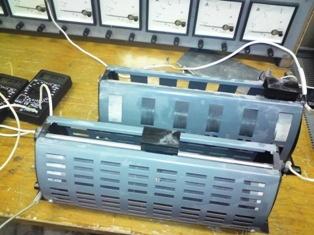
Air-cooled metal rheostats gained the greatest distribution. They are the easiest to adapt to different operating conditions, both in terms of electrical and thermal characteristics, and in terms of different design parameters. Rheostats can be made with continuous or stepwise change of resistance.
Wire rheostat
The step switch in rheostats is flat.In a flat switch, the movable contact slides over the fixed contacts while moving in the same plane. Fixed contacts are made in the form of bolts with flat cylindrical or hemispherical heads, plates or tires arranged along the arc of a circle in one or two rows. A movable sliding contact, commonly called a brush, can be of the bridge or lever type, self-aligning or non-aligning.
A non-aligning movable contact is simpler in design but unreliable in operation due to frequent contact failure. With a self-regulating movable contact, the required contact pressure and high operational reliability are always ensured. These contacts became widespread.
The advantages of the flat step rheostat switch are relative simplicity of construction, relatively small dimensions with a large number of steps, low cost, the ability to mount contactors and relays on the switchboard to switch off and protect controlled circuits. Disadvantages — relatively low switching power and low breaking power, high brush wear due to sliding friction and melting, difficulty in using for complex connection schemes.
Oil-cooled metal rheostats provide increased heat capacity and constant heat-up time due to the high heat capacity and good thermal conductivity of the oil. This allows in short-term modes to sharply increase the load on the resistors and, therefore, to reduce the consumption of resistive material and the dimensions of the rheostat. Oil-immersed elements should have as large a surface area as possible to ensure good heat dissipation.It is not recommended to immerse closed resistors in oil. Oil immersion protects resistors and contacts from harmful environmental influences in the chemical and other industries. Only resistors or resistors and contacts can be immersed in oil.
The breaking capacity of contacts in oil is increased, which is an advantage of these rheostats. The transient resistance of the contacts in the oil increases, but at the same time the cooling conditions are improved. In addition, large contact presses can be tolerated due to lubrication. The presence of lubricant ensures low mechanical wear.
For long-term and intermittent modes of operation, oil-cooled rheostats are unsuitable due to the low heat transfer from the tank surface and the long cooling time. They are used as starting rheostats for wound-rotor asynchronous electric motors up to 1000 kW with infrequent starts.
The presence of oil also creates a number of disadvantages: contamination of the premises, increased risk of fire.
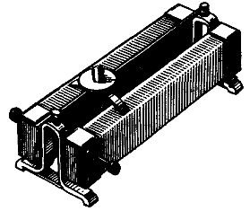
Rice. 1. Rheostat with continuously changing resistance
An example of a rheostat with an almost continuous change in resistance is shown in fig. 1. On the frame 3 of heat-resistant insulating material (steatite, porcelain), a resistor wire is wound. To isolate the turns from each other, the wire is oxidized. A spring contact 5 slides over a resistor and a guide current-carrying rod or ring 6, connected to the movable contact 4 and moved by means of an insulated rod 8, at the end of which an insulated handle is placed (the handle is removed in the figure). Housing 1 is used to assemble all parts and fix the rheostat, and plates 7 for external connection.
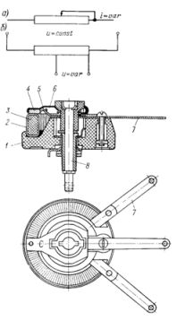
Rheostats can be included in the circuit as a variable resistor (Fig. 1, a) or as potentiometer(Fig. 1.6). Rheostats provide smooth control of resistance, and, therefore, current or voltage in a circuit and are widely used in laboratory settings in automatic control circuits.
Schemes for inclusion of starting and regulation of rheostats
Image 2 shows a switching circuit using a rheostat for a low power DC motor.
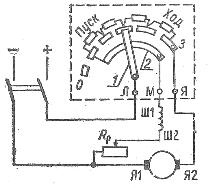
Rice. 2… Rheostat switching circuit: L — clamp connected to the network, I — clamp connected to the armature; M — clamp connected to the excitation circuit, O — empty contact, 1 — arc, 2 — lever, 3 — working contact.
Before turning on the engine, make sure that the lever 2 of the rheostat is at the empty contact 0. Then the switch turns on and the rheostat lever is transferred to the first intermediate contact. In this case, the motor is excited and a starting current appears in the armature circuit, the value of which is limited by the four sections of the resistance Rp. As the frequency of rotation of the armature increases, the inrush current decreases and the rheostat lever is transferred to the second, third contact, etc., until it is not at the working contact.
Starting rheostats are designed for short-term operation, and therefore the rheostat lever cannot be delayed for a long time on intermediate contacts: in this case, the rheostat resistances overheat and may burn out.
Before disconnecting the motor from the mains, it is necessary to move the handle of the rheostat to the extreme left position. In this case, the motor is disconnected from the mains, but the field winding circuit remains closed to the resistance of the rheostat.Otherwise, large overvoltages may occur in the excitation coil at the moment of opening the circuit.
When starting DC motors, the control rheostat in the field winding circuit must be fully pulled out to increase the field flux.
To start motors with series excitation, use double-clamp starting rheostats, differing from three clamps in the absence of a copper arc and the presence of only two clamps - L and Ya.
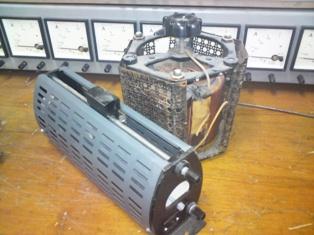
Rheostats with a step change of resistance (oriz. 3 and 4) consists of a set of resistors 1 and a device for step switching.
The switching device consists of fixed contacts and a movable sliding contact and drive. In the ballast rheostat (Fig. 3), the L1 pole and the armature pole I are connected to the fixed contacts, the taps from the resistance elements, starting and regulating, according to the stage breakdown, and other circuits controlled by the rheostat. The movable sliding contact closes and opens the stages of resistance as well as all other circuits controlled by the rheostat. The drive of the rheostat can be manual (using the handle) and motorized.
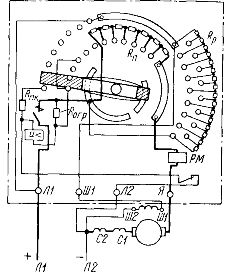
Rice. 3... Connection diagram of the rheostat at start: Rpc - resistor shunting the contactor coil in the off position of the rheostat, Rogr - resistor limiting the current in the coil, Ш1, Ш2 - parallel DC motor excitation winding, C1, C2 - series excitation winding of a DC motor.
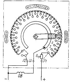
Rice. 4… Excitation Control Rheostat Connection Diagram: Rpr — Upstream Resistance, OB — DC Motor Excitation Coil.
Rheostats of the type shown in fig. 2 and 3 are widespread.However, their designs have some disadvantages, in particular a large number of fasteners and wiring, especially in excitation rheostats that have a large number of stages.
A circuit diagram of an oil-filled rheostat of the RM series, designed for starting wound-rotor induction motors, is shown in Fig. 5. Voltage in the rotor circuit up to 1200 V, current 750 A. Durability of switching 10,000 operations, mechanical — 45,000. The rheostat allows 2 — 3 starts in one row.
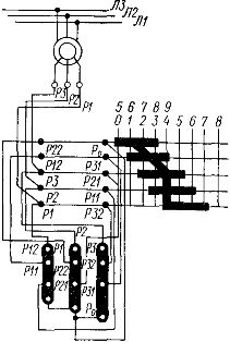
Rice. 5 Circuit diagram of an oil-filled regulating rheostat
The rheostat consists of resistor packs and a switching device built into the tank and immersed in oil. Resistor packs are assembled from elements stamped from electrical steel and attached to the tank cover. The switching device is of the drum type, it is an axis with segments of a cylindrical surface fixed on it, connected according to a certain electrical circuit. The fixed contacts connected to the resistor elements are fixed on a fixed busbar. When the drum axis is rotated (by flywheel or motor drive), the segments as movable sliding contacts overcome certain fixed contacts and thus change the resistance value in the rotor circuit.