Schemes for turning on fluorescent lamps with electromagnetic ballasts
dTo maintain and stabilize the discharge process, in series with the fluorescent lamp, the ballast resistance in the alternating current network is included in the form he choked or choke and capacitor... These devices are called ballasts (ballasts).
The mains voltage at which the fluorescent lamp operates in a steady state is insufficient to ignite. For the formation of a gas discharge, that is, the breakdown of the gas space, it is necessary to increase the emission of electrons by preheating or by applying a pulse of increased voltage to the electrodes. Both are provided by a starter connected in parallel with the lamp.
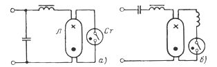
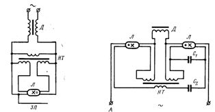
Scheme of switching on a fluorescent lamp: a — with inductive ballast, b — with inductive-capacitive ballast.
Consider the process of lighting a fluorescent lamp.
A starter is a miniature glow discharge neon lamp with two bimetallic electrodes that are normally open.
 When voltage is applied to the starter, a discharge occurs and the bimetallic electrodes, bending, are short-circuited.After they close, the current in the starter and electrode circuit, limited only by the choke resistance, increases to two or three times the lamp's operating current, and the fluorescent lamp's electrodes quickly heat up. At the same time, the bimetallic electrodes of the starter, cooling down, open its circuit.
At the moment when the circuit is broken by the starter, an increased voltage pulse occurs in the choke, as a result of which a discharge occurs in the gaseous medium of the fluorescent lamp and its ignition. After the lamp is lit, the voltage in it is about half of the mains voltage. This voltage will be on the starter, but it is not enough to close it again. Therefore, when the lamp is on, the starter is open and does not participate in the operation of the circuit.
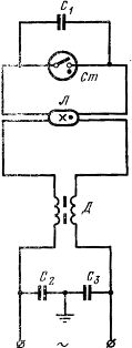
One-lamp starter circuit for turning on a fluorescent lamp: L — fluorescent lamp, D — choke, St — starter, C1 — C3 — capacitors.
A capacitor in parallel with the starter and capacitors at the circuit input are designed to reduce RFI. A capacitor connected in parallel with the starter also helps to increase the life of the starter and affects the lamp ignition process, contributing to a significant reduction of the voltage pulse in the starter (from 8000 -12000 V to 600-1500 V), while increases the pulse energy (by increasing its duration).
 The disadvantage of the described starter circuit is the low cos phi, which does not exceed 0.5. Increasing cos phi is achieved either by including a capacitor at the input or by using an inductive-capacitive circuit.In this case, however, cos phi 0.9 — 0.92 as a result of the presence of higher harmonic components in the current curve, determined by the specifics of the gas discharge and the control device.
In two-lamp luminaires, reactive power compensation is achieved by switching one lamp with an inductive ballast and the other with an inductive-capacitive ballast. In this case cos phi = 0.95. In addition, such a circuit of a control device allows to smooth out to a large extent the pulsations of the luminous flux of fluorescent lamps.
Scheme for switching on fluorescent lamps with split phases
The most widely used for turning on fluorescent lamps with a power of 40 and 80 W is a two-lamp pulse ignition starter circuit using ballast compensation devices 2UBK-40/220 and 2UBK-80/220 operating according to a «split phase» scheme . They are complete electrical devices with chokes, capacitors and discharge resistors.
In series with one of the lamps, only the inductive resistance of the choke is turned on, creating a phase lag of the current from the applied voltage. In series with the second lamp, in addition to the choke, a capacitor is also connected, the capacitive resistance of which is approximately 2 times greater than the inductive resistance of the choke, which creates a current advance, as a result of which the total power factor of the set is about 0 .9 -0.95.
In addition, the inclusion of a specially selected capacitor in series with the choke of one of the two lamps provides such a phase shift between the currents of the first and second lamps that the depth of oscillation of the total luminous flux of the two lamps will be significantly reduced.
To increase the current for heating the electrodes, the compensating coil is connected in series with the tank, which is turned off by the starter.
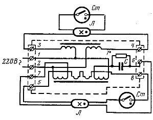
Connection diagram for turning on a two-lamp starter 2UBK: L — fluorescent lamp, St — starter, C — capacitor, r — discharge resistance. The case of PRA 2UBK is shown by the dashed line.
Schemes without a starter for turning on fluorescent lamps
The disadvantages of starter switching circuits (significant noise generated by ballasts during operation, flammability during emergency modes, etc.), as well as the low quality of manufactured starters, have led to constant searches for economically viable rational ballasts, which are non-bootable to be applied mostly in installations where they are quite simple and cheap.
For reliable operation of starless circuits, it is recommended to use lamps with a conductive strip attached to the bulb.
The most common are fast-start transformer circuits for fluorescent lamps in which a choke is used as a ballast resistance, and the cathodes are preheated by an incandescent transformer, or autotransformer.
Starless circuits with one and two lamps for switching on fluorescent lamps: L - fluorescent lamp, D - choke, NT - incandescent transformer
Currently, calculations have established that starting schemes for indoor lighting are more economical, and therefore they are widespread. In the starter circuits, energy losses are approximately 20 - 25%, in non-starters - 35%
Recently, schemes for turning on fluorescent lamps with electromagnetic ballasts are gradually being replaced by schemes with more functional and economical electronic ballasts (ECG).
When calculating lighting networks with fluorescent lamps, it should be borne in mind that even with compensated circuits without ballasts, the phase shift cannot be completely eliminated. Therefore, when determining the estimated current of networks with fluorescent lamps, it is necessary to take cosine phi = 0.9 for circuits with reactive power compensation, and cosine phi = 0.5 in the absence of capacitors in circuits. In addition, it is necessary to take into account the power losses in the control device.
When choosing cross-sections for four-wire networks with fluorescent lamps, some characteristics of such networks should be taken into account. The fact is that the non-linearity of the current-voltage characteristics of fluorescent lamps, as well as the presence of an inductor with a steel core and capacitors in their purpose, lead to a non-sinusoidal current curve and, as a result, the appearance of higher harmonics, which significantly change the current of the neutral conductor even with a uniform phase load.
The current in the neutral wire can reach values close to the current in the phase wire 85-87% of Aze. This implies the need to choose the cross-section of the neutral wire in four-wire networks with fluorescent lighting equal to the cross-section of the phase wires, and when laying wires in pipes, the permissible current load should be taken as for four wires in one pipe.