Instrument voltage transformers
Purpose and principle of operation of the voltage transformer
The measuring voltage transformer is used to step down the high voltage supplied in AC installations to meters and relays for protection and automation.
A direct high voltage connection would require very cumbersome devices and relays due to the need to implement them with high voltage insulation. The production and use of such equipment is practically impossible, especially at voltages of 35 kV and above.
The use of voltage transformers allows the use of standard measuring devices to measure high voltage, expanding their measurement limits; relay coils connected via voltage transformers can also have standard versions.
In addition, the voltage transformer isolates (separates) the measuring devices and relays from the high voltage, thereby ensuring the safety of their service.
Voltage transformers are widely used in high voltage electrical installations, accuracy depends on their operation electrical measurements and electricity metering, as well as the reliability of relay protection and emergency automation.
The measuring voltage transformer, according to the design principle, does not differ from power supply step-down transformer… It consists of a steel core consisting of electrical steel sheet plates, a primary winding and one or two secondary windings.
In fig. 1a shows a schematic diagram of a voltage transformer with a single secondary winding. A high voltage U1 is applied to the primary winding and a measuring device is connected to the secondary voltage U2. The beginning of the primary and secondary windings is marked with the letters A and a, the ends with X and x. Such designations are usually applied to the body of the voltage transformer next to the terminals of its windings.
The ratio of the rated voltage of the primary to the rated voltage of the secondary is called the rated voltage. transformation factor voltage transformer Kn = U1nom / U2nom
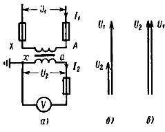
Rice. 1. Scheme and vector diagram of the voltage transformer: a — diagram, b — voltage vector diagram, c — voltage vector diagram
When a voltage transformer operates without errors, its primary and secondary voltages match in phase and the ratio of their values is equal to Kn. With a transformation factor Kn = 1 voltage U2= U1 (Fig. 1, c).
Legend: H — one terminal is grounded; O — single-phase; T — three-phase; K — cascade or with compensation coil; F — s porcelain outer insulation; M — oil; C — dry (with air insulation); E — capacitive; D is a divisor.
The primary winding (HV) terminals are labeled A, X for single-phase and A, B, C, N for three-phase transformers. Main terminals of the secondary winding (LV) are respectively marked a, x and a, b, c, N, terminals of the secondary additional winding — ad techend.
At first the primary and secondary windings are connected to terminals A, B, C and a, b, c respectively. The main secondary windings are usually connected in a star (connection group 0), additional - according to the open delta scheme. As you know, during normal operation of the network, the voltage at the terminals of the additional winding is close to zero (unbalanced voltage Unb = 1 — 3 V), and for earth faults it is equal to three times the value of 3UО voltage with zero sequence UО phase.
In a network with a grounded neutral, the maximum value is 3U0 equal to the phase voltage, with isolated - three-phase voltage stress. Accordingly, additional windings of rated voltage Unom = 100 V and 100/3 V are performed.
Rated voltage TV is its rated voltage primary winding; this value may differ from the insulation class. The nominal voltage of the secondary winding is assumed to be 100, 100/3 and 100/3 V. Normally, voltage transformers operate in the no-load mode.
Instrument voltage transformers with two secondary windings
 Voltage transformers with two secondary windings, in addition to powering meters and relays, are designed to operate earth fault signaling devices in a network with an isolated neutral or for earth fault protection in a network with an earthed neutral.
A schematic diagram of a voltage transformer with two secondary windings is shown in Fig. 2, a. The terminals of the second (additional) winding, used for signaling or protection in case of earth faults, are labeled ad and xd.
In fig. 2.6 shows a diagram of the inclusion of three such voltage transformers in a three-phase network. The primary and main secondary windings are star connected. The neutral of the primary winding is grounded. Three phases and neutral can be applied to meters and relays from the main secondary windings. Additional secondary windings are connected in open delta. From these, the sum of the phase voltages of all three phases is fed to the signaling or protective devices.
In normal operation of the network in which the voltage transformer is connected, this vector sum is zero. This can be seen from the vector diagrams in fig. 2, c, where Ua, Vb and Uc are the vectors of phase voltages applied to the primary windings, and Uad, Ubd and Ucd — voltage vectors of the primary and secondary additional windings. voltages of the secondary additional windings, coincident in direction with the vectors of the corresponding primary windings (the same as in Fig. 1, c).
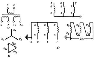
Rice. 2. Voltage transformer with two secondary windings. a — diagram; b — inclusion in a three-phase circuit; c — vector diagram
The sum of vectors Uad, Ubd and Ucd are obtained by combining them according to the scheme of connecting additional windings, while it is assumed that the arrows of the vectors of both primary and secondary voltages correspond to the beginning of the transformer windings.
The resulting voltage 3U0 between the end of the phase C winding and the beginning of the phase A winding in the diagram is zero.
Under actual conditions, there is usually a negligible unbalance voltage at the output of an open delta, not exceeding 2 to 3% of the rated voltage. This imbalance is created by the ever-present slight asymmetry of the secondary phase voltages and a slight deviation of the shape of their curve from the sinusoid.
The voltage guaranteeing the reliable operation of the relays applied to the open delta circuit appears only in the event of earth faults on the side of the primary winding of the voltage transformer. Since earth faults are associated with the passage of current through the neutral, the resulting voltage at the output of the open delta according to the method of symmetrical components is called the zero-sequence voltage and is denoted 3U0. In this notation, the number 3 indicates that the voltage in this circuit is the sum of three phases. The designation 3U0 also refers to the open delta output circuit applied to the alarm or protection relay (Fig. 2.6).
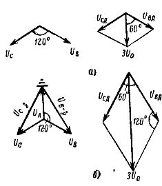
Rice. 3. Vector diagrams of the voltages of the primary and secondary additional windings with a single-phase earth fault: a — in a network with a grounded neutral, b — in a network with an isolated neutral.
The voltage 3U0 has the highest value for a single-phase earth fault.It should be taken into account that the maximum value of the voltage 3U0 in a network with an isolated neutral is much higher than in a network with an earthed neutral.
General switching schemes of voltage transformers
The simplest scheme using one single phase voltage transformershown in fig. 1, a, is used when starting motor cabinets and at switching points 6-10 kV to turn on the voltmeter and voltage relay of the AVR device.
Figure 4 shows the connection diagrams for single-phase single-winding voltage transformers for supplying three-phase secondary circuits. A group of three star single-phase transformers shown in Fig. 4, a, is used to power measuring devices, measuring devices and voltmeters for insulation monitoring in electrical installations of 0.5-10 kV with an isolated neutral and unbranched network, where signaling of the occurrence of single-phase grounding is not required.
In order to detect "earth" on these voltmeters, they must show the magnitude of the primary voltages between the phases and earth (see the vector diagram in Fig. 3.6). For this purpose, the neutral of the HV windings is earthed and the voltmeters are connected to the secondary phase voltages.
Since in the case of single-phase earth faults, voltage transformers can be energized for a long time, their rated voltage must match the first line-to-line voltage. As a result, in normal mode, when operating at phase voltage, the power of each transformer, and therefore of the entire group, decreases by √3 once. Since the circuit has zero secondary windings grounded, secondary fuses are installed in all three phases.
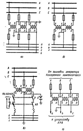
Rice. 4.Connection diagrams of single-phase voltage measuring transformers with one secondary winding: a — star-star circuit for electrical installations of 0.5 — 10 kV with isolated zero, b — open delta circuit for electrical installations 0.38 — 10 kV, c — the same for electrical installations 6 — 35 kV, d — inclusion of voltage transformers 6 — 18 kV according to the triangular star scheme for powering the ARV devices of synchronous machines.
In fig. 4.6 and voltage transformers designed to power measuring devices, meters and relays connected to phase-phase voltage are connected in an open delta circuit. This scheme provides symmetrical voltage between lines Uab, Ubc, U°Ca when operating voltage transformers in any class of accuracy.
Function open delta circuit this is an insufficient use of the power of transformers, because the power of such a group of two transformers is less than the power of a group of three transformers connected in a complete triangle not by 1.5 times, but by √3 once .
The diagram in fig. 4, b is used to supply unbranched voltage circuits of electrical installations 0.38 -10 kV, which allows the grounding of the secondary circuits to be installed directly to the voltage transformer.
In the secondary circuits of the circuit shown in fig. 4, c, instead of fuses, a double-pole breaker is installed, when it is triggered, the contact of the block closes the signal circuit «voltage interruption»... The grounding of the secondary windings is carried out on the shield in phase B, which is additionally grounded directly to the voltage transformer through failure fuse.The switch ensures disconnection of the secondary circuits of the voltage transformer with a visible break. This scheme is used in electrical installations 6 — 35 kV when feeding branched secondary circuits from two or more voltage transformers.
In fig. 4, g voltage transformers are connected according to the delta circuit — star, providing a voltage on the secondary line U = 173 V, which is necessary for powering automatic excitation control devices (ARV) of synchronous generators and compensators. To increase the reliability of ARV operation, fuses in the secondary circuits are not installed, which is allowed PUE for unbranched voltage circuits.
See also: Connection diagrams of measuring voltage transformers