Single-phase and two-phase asynchronous motors
Purpose, device and principle of operation of single-phase asynchronous motors
Single-phase induction motors are low-power machines that resemble similar three-phase squirrel-cage motors in design.
Single-phase asynchronous motors differ from three-phase motors in the stator arrangement, where a two-phase winding is located in the grooves of the magnetic circuit, consisting of the main or working phase with a phase area of 120 el. hail and leads to terminals marked C1 and C2, and an auxiliary or starting phase with a phase area of 60 el. hail and leads to terminals marked B1 and B2 (Fig. 1).
The magnetic axes of these winding phases are offset relative to each other by an angle 0 = 90 el. hail. A working phase connected to the alternating voltage network cannot cause the rotor to rotate, since its current excites an alternating magnetic field with a fixed axis of symmetry, characterized by a magnetic induction harmonically changing in time.
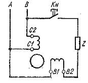
Rice. 1. Circuit diagram of a single-phase squirrel-cage rotor induction motor.
This field can be represented by two components — identical circular magnetic fields of direct and reverse sequence, rotating with magnetic inductions, rotating in opposite directions at the same speed. However, when the rotor is pre-accelerated in the required direction, it continues to rotate in the same direction when the working phase is turned on.
 For this reason, the starting of a single-phase motor begins by accelerating the rotor by pressing the start button, causing currents to be excited in both phases of the stator winding, which are phase-shifted by an amount depending on the parameters of the phase-shifting device Z, made in the form of a resistor, an inductor or a capacitor, and electrical circuit elements that include the operating and starting phases of the stator winding. These currents cause a rotating magnetic field in the machine with magnetic induction in the air gap, which periodically and monotonically changes within the maximum and minimum values, and the end of its vector describes an ellipse.
It. The elliptical rotating magnetic field detects EMF and currents in the wires of the short-circuited rotor winding, which, interacting with this field, ensure the acceleration of the rotor of the single-phase motor in the direction of rotation of the field, and it reaches almost nominal speed in a few seconds.
Releasing the start button transfers the electric motor from the two-phase mode to the single-phase mode, which is additionally supported by the corresponding component of the alternating magnetic field, which during its rotation is slightly ahead of the rotating rotor due to slip.
Timely disconnection of the starting phase of the stator winding of a single-phase asynchronous motor from the power network is necessary due to its design, which provides for a short-term mode of operation - usually up to 3 s, which excludes its prolonged stay under load due to unacceptable overheating, insulation burning and damage .
Increasing the reliability of operation of single-phase asynchronous motors is provided by embedding in the machine case a centrifugal switch with interrupting contacts connected to terminals marked VT and B2 and a thermal relay with similar contacts having terminals marked PT and C1 (Fig. 2, c, d).
The centrifugal switch automatically disconnects the starting phase of the stator winding connected to the terminals marked B1 and B2 when the rotor reaches a speed close to the rated one, and the thermal relay disconnects both phases of the stator winding from the mains when the heating is higher of the permissible.
The reversal of the direction of rotation of the rotor is achieved by changing the direction of the current in one of the phases of the stator winding when starting by switching the start button and rearranging the metal plate on the terminals of the electric motor ( Fig. 2, a, b) or only by rearranging two similar plates (Fig. 2, c, d).
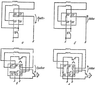
Rice. 2. Marking of the terminals of the phases of the stator winding of a single-phase asynchronous motor with a squirrel rotor and their connection for rotor rotation: a, c — right, b, d — left.
Comparison of the technical characteristics of single-phase and three-phase asynchronous motors
Single-phase asynchronous motors differ from three-phase machines similar in rated power with a reduced initial torque factor kn = МХ / Mnom and an increased initial current factor ki = Mi / Mnom, which are for single-phase electric motors with an initial phase of the stator winding with increased direct current resistance and lower inductance of the working phase are important kn — 1.0 — 1.5 and ki = 5 — 9.
The starting characteristics of single-phase asynchronous motors are worse than those of three-phase asynchronous motors due to the fact that an elliptical rotating magnetic field is excited at the start of single-phase machines with an initial phase of the stator winding equivalent to two non-uniform circular rotating magnetic fields — directly and vice versa, causes a braking effect.
 By selecting the parameters of the elements of the electrical circuits of the working and starting phase of the stator winding, it is possible to ensure the excitation of a circular rotating magnetic field at start-up, which is possible with a phase-shifting element made in the form of a capacitor with a suitable capacity.
As the acceleration of the rotor causes a change in the parameters of the machine circuits, the rotating magnetic field changes from circular to elliptical, thus degrading the starting characteristics of the motor. Therefore, at a speed of about 0.8 nominal, the starting phase of the stator winding of the electric motor is switched off manually or automatically, as a result of which the motor switches to single-phase operation.
Single-phase asynchronous motors with a starting capacitor have a multiple of the initial starting torque kp = 1.7 — 2.4 and a multiple of the initial starting current ki = 3 — 5.
Two-phase asynchronous motors
In two-phase asynchronous motors, the two phases of the stator winding with phase areas of 90 el. greetings are the workers. They are located in the grooves of the magnetic circuit of the stator, so that their magnetic axes form an angle of 90 el. hail. These phases of the stator winding differ from each other not only in the number of turns, but also in rated voltages and currents, although their total powers are the same at the rated mode of the motor.
In one of the phases of the stator winding there is a permanent capacitor Cp (Fig. 3, a), which under the conditions of the nominal mode of the motor provides excitation of a circular rotating magnetic field. The capacity of this capacitor is determined by the formula:
° Cp = I1sinφ1 / 2πfUn2
where I1 and φ1- respectively the current and phase shift between the voltage and current of the phase circuit of the stator winding without a capacitor in a circular rotating magnetic field, I and ti — the frequency of the alternating current and the voltage of the supply network, respectively, n- transformation coefficient — the ratio of the effective number of turns of the phases of the stator winding, respectively with and without a capacitor, determined by the formula
n = kvol2 w2 / ktom 1 w1
where коб2 and коб1 — winding coefficients of the corresponding phases of the stator winding with the number of turns w2 and w1.
Capacitor terminal voltage Uc connected in series with the winding phase of a two-phase induction motor with a circular rotating magnetic field above the mains voltage U and is determined as follows:
Uc = U √1 + n2
The transition to a motor load other than the nominal one is accompanied by a change in the rotating magnetic field, which instead of circular becomes elliptical.This worsens the working properties of the engine, and when starting, it reduces the initial Starting torque to MP <0.3Mnom, limiting the use of permanently connected capacitor motors only in installations with mild starting conditions.
To increase the initial torque, the starting capacitor Cn is connected in parallel with the working capacitor Cp (Fig.3, b), the capacity of which is much greater than the capacity of the working capacitor and depends on the set of the initial starting torque, which can be increased to two or more.
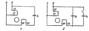
Rice. 3. Schemes for switching on two-phase asynchronous motors with a squirrel-cage rotor: a — with a permanently connected capacitor, b — with a running and starting capacitor.
After the rotor accelerates to a speed of 0.6 — 0.7 of the nominal starting capacitor, it is turned off to avoid the transition of a circular rotating magnetic field into an elliptical one, which deteriorates the operation of the motor.
The starting mode of such capacitor motors is characterized by the following parameters: kn = 1.7 — 2.4 and ki = 4 — 6.
Capacitor motors are distinguished by better energy characteristics than single-phase motors with an initial veil on the stator winding, and their power factor, thanks to the use of capacitors, is higher than that of three-phase motors of the same power.
Universal asynchronous motors
Automatic control installations use universal asynchronous motors-three-phase machines of low power, which are connected to a three-phase or single-phase network. When powered from a single-phase network, the starting and operating characteristics of motors are slightly worse than when used in three-phase mode.
Universal asynchronous motors of the UAD series are produced with two- and four-poles, which in three-phase mode have a nominal power of 1.5 to 70 W, and in single-phase mode - from 1 to 55 W and operate from an alternating voltage network with a frequency of 50 Hz with efficiency η= 0.09 — 0.65.
Single-phase asynchronous motors with shaded or shaded poles
In single-phase induction motors with split or shaded poles, each pole is divided by a deep groove into two unequal parts and carries a single-phase winding covering the entire magnetic circuit of the pole and short-circuited turns located on its smaller part.
The rotor of these motors has a short circuit winding. The inclusion of the stator winding to a sinusoidal voltage is accompanied by the establishment of a current in it and the excitation of an alternating magnetic field with a fixed axis of symmetry, which induces the corresponding emf and currents in the short-circuited loops.
Under the influence of short-circuit currents, the corresponding m.d.s excite a magnetic field, which prevents the strengthening and weakening of the main magnetic field in shielded frequent poles. The magnetic fields of the shielded and unshielded parts of the poles are out of phase in time and, shifted in space, form the resulting elliptical rotating magnetic field moving in the direction from the magnetic axis of the unshielded part of the pole to the magnetic axis of its shielded part.
The interaction of this field with the currents induced in the rotor winding causes the appearance of the initial torque Mn = (0.2 — 0.6) Mnom and the acceleration of the rotor to the rated speed, if the braking torque applied to the motor shaft should not to exceed the starting torque.
To increase the initial starting and maximum torques of single-phase asynchronous motors with split or shaded poles, magnetic shunts of steel sheet are placed between their poles, which brings the rotating magnetic field closer to circular.
Shaded pole motors are non-reversible devices that allow frequent starts, sudden stops and can be delayed for a long time. They are made with two- and four-pole rated power from 0.5 to 30 W and with an improved design up to 300 W for operation from an alternating voltage network with a frequency of 50 Hz with an efficiency of ηnom = 0.20 — 0.40.
Read also: Selsyns: purpose, device, principle of action