Electrical equipment and chains of electric hoists
Purpose and device of electric hoists
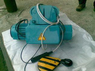
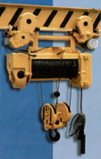
Electric hoist — this is a winch of small dimensions, all elements of which (electric motor, reducer, brake, rope drum with thread for laying the rope, cabinet with starting equipment and other necessary devices) are installed in one body or attached to this body. The electric hoist also includes a monorail undercarriage and hook suspension. As a rule, hoists are equipped with a pendant for control from the floor.
Manual hoists and car jacks aside, electric hoists are the most widely used hoists in the world.
Electric hoists are designed for lifting and horizontal movement of loads on the monorail indoors and under a canopy at an ambient temperature of -20 (-40) to + 40 ° C.
Hoists are used as part of suspended and supporting single-nose, cantilever, gantry and other cranes, as well as monorails and independently.
Until the early 1990s, a large number of lifting and transport equipment was produced in the Soviet Union, but the demand for this equipment always exceeded production. 160-180 thousand electric hoists were distributed. per year (including about half of the production in Bulgaria), and consumers asked for twice as much. The majority of electric hoists are used to equip one-way and jib cranes.
Electrical equipment of electric hoists
The electrical diagrams of the hoists of different designs have many common and noticeable differences. They show the principle of construction and operation of the electrical equipment of the lifts.
The lifts are powered by three-phase alternating current with a voltage of 380V and a frequency of 50Hz.
On electric hoists, magnetic reversing starters without thermal protection with electrical blocking.
Electric hoists are manually operated from the floor via suspended control post with a button… The design of the push-button rack is such that activation of the lifting mechanisms is only possible by continuously pressing the button.
The scheme for turning on the contacts of the buttons of the control station provides for electrical blocking, which excludes the possibility of simultaneous activation of the starters when pressing the buttons intended to turn on the opposite movements of the same mechanism. This does not exclude the possibility of simultaneously activating different mechanisms (combining movement with lifting or lowering the load). In the schematic diagrams presented, the designations of the elements used in the operating manuals have been preserved.
Electrical diagrams of the hoists
Schematic electrical diagram of a 5.0 t lift from the Slutsk Industrial Equipment Plant (developed in 1999).
The electric hoist is equipped with a disc brake, switches for the upper and lower position of the hook suspension, an emergency switch for the upper position of the suspension. Control circuit 42 V.
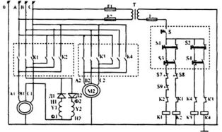
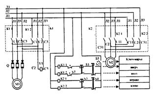
Schematic diagram of a 5.0 t lift from the PTO plant in Slutsk
Power to the hoist must be provided through a four-core cable, one of which is a ground cable. When trolling for food you must have a fourth hoist, ground wire.
The hoist control circuit operates at a safe low voltage of 42V, which is obtained by means of a transformer (T) with separate windings connected to phases A and C. The secondary winding of the transformer (T) must be earthed.
Fuses (F1, F2, F3) protect the transformer windings. The switch (S) on the PKT-40 control station ensures that the hoist control system is turned on and voltage is applied to starters with magnetic motors.
The hoist control buttons (on the rack) (S1, S2, S3, S4) provide current to the coils (K1, K2, KZ, K4) of the corresponding magnetic starter. Due to its design, each button element provides the first stage of electrical blocking from the simultaneous activation of reversing starters on one engine. The second stage of electrical blocking with the same function is provided by normally closed contacts of starters (K1, K2, K3, K4). The limit switches (S7, S8) interrupt the electrical circuit of the coils (K2-K1, K4-KZ).
The switches (S7, S8) are actuated by a rope laying circuit via a mechanical kinematic circuit.Switch (S9) duplicates the action of switch (S7). The braking coil is included in the section of phase B, there are two sections that are wound with two parallel wires and switched so that the beginning of one (H2) is connected to the end of the other (F1), forming one common terminal, and the others ends of sections (F1 and F2) connected to diodes (D1 and D2). The power section of the circuit provides power to the motors. This is done using the contact part of the reversing starters K1-K2 and KZ-K4.
Schematic circuit diagram of 0.25 ton hoists from the Poltava plant (development since the early 1970s)
The electric hoists are equipped with a disc brake, switches for the upper and lower position of the hook suspension and an emergency switch for the upper position of the suspension. 42V control circuit
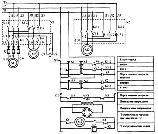
Schematic diagram of electric hoists with a load capacity of 0.25 and 0.5 tons equipped with a drive device.
Schematic diagram of 0.25 and 0.5 t hoists not equipped with travel drive
Schematic diagram of lifts with a load capacity of 3.2 t at the Barnaul Plant for Metal Cutting Machines
The digitizer of the lifting mechanism of the hoist is pressed into the drum. The hoists are equipped with a column brake, a switch for the upper suspension bracket (they can be equipped with switches for the upper and lower position of the hook suspension, which are actuated by a rope laying device). No undervoltage is provided for the control circuit. Basic version with one lifting speed.
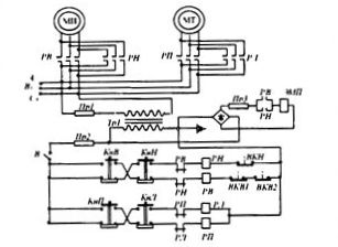
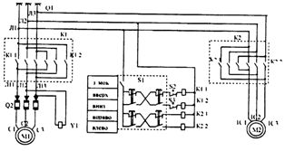
Electrical schematic diagram of 3.2 t hoists without micro drive
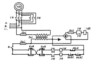
Electrical schematic diagram of a 3.2 t micro-drive hoist
Schematic diagram of hoists with a load capacity of 5.0 t
Schematic diagram of 5.0 ton hoists from the Kharkiv PTO Plant
Schematic diagram of 3.2 and 5.0 ton hoists of the Uryupin Crane
The hoists are equipped with a limit switch for the upper position of the hook block. The hoists intended for the installation of single-nose cranes are equipped with a control panel with six buttons.
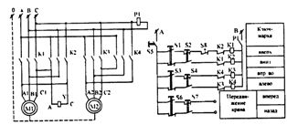
Schematic diagram of 3.2 and 5.0 ton hoists of the Uryupin Crane
Current wire to electric hoists
The current supply of the lifts is carried out in most cases via a flexible cable (Figure 4.8). Food carts are also available.
A flexible cable (1) used to power the hoist (four-core copper, flexible in rubber insulation) can have a current wire length of up to 25-30 m, suspended by rings on a string (2) . This design is shown in the figure.
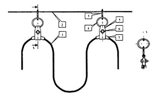
Power wire to hoists with flexible cable
Steel or brass wire or 5 mm steel rope is used as rope. Rings (3 and 4) — 40 ... 50 mm. The clamps (5) must not have sharp edges and are equipped with a clamping bolt (6). The lining (7) can be made of a rubber tube.
The distance between hangers with a stretched cable should be within 1400 — 1800 mm. To prevent the cable from breaking, a mild steel cable with a diameter of about 2.5 mm is fixed together with it in the clamps, the length of which is slightly less than the length of the cable itself, so that the tension is transmitted through the cable and not through the cable .
 If the travel path of the hoist is within 30-50 m, an I-beam or other rigid guide is used as a guide. In this case, the cable is hung on roller hangers.
If the travel distance of the hoist exceeds 50 m, the possibility of using a simple and inexpensive cable current conductor should be checked by calculation. The calculation must confirm the admissibility of the loss value in a long cable and the ability of the hoist without load to overcome the resistance to movement of rings or carriages along the entire length of the current conductor. In some cases, with a small cross-section of the conductors of the power supply cable (with low transmitted power), with artificial weighing of the hoist without a load, etc. it is possible to increase the length of the cable current conductor to 60 and more m.
With bogie power, which is used for long travel distances of the hoists and when operating the hoists on curved tracks (as part of monorails or independently), the pantograph can be installed on both sides of the monorail. For feeding a trolley, a small-sized closed bus channel or a trolley path, made according to the project in compliance with PUE.
Zertsalov A. I. Electric rope hoists and cranes with hoists