Cyclograms of the operation of electrical equipment on the diagrams
 For more complete information about the principle of operation of blocks and individual devices of metal-cutting machines and installations, the schematic circuit diagram is often supplemented with cyclograms.
Cyclogram — cyclic diagram, graphical representation of a cyclic process.
Cyclograms (tactograms) of the operation of electrical equipment are intended to explain and determine the sequence and duration of inclusion of electric motors and control equipment. They are necessary to clarify and determine the sequence and duration of inclusion of electric motors and control equipment in the cycles of mechanisms.
It is important to have cyclograms for mechanisms with automatic duty cycles and a large number of control devices. As a rule, cyclograms show motion switches, pressure switches, electromagnets and other command and executive devices or electric motors.
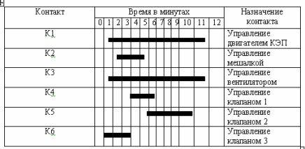
Rice. 1. Example of a cyclogram
There are two main ways to draw cyclograms — tabular and graphical.The tabular method is usually used to explain the operation of hydraulic or pneumatic-electric control elements.
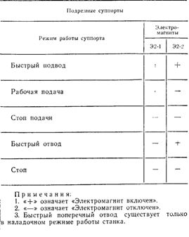
When compiling cyclograms according to the tabular method, it is necessary to adhere to the following conventions:
a) the «+» sign means forced state of the device.
This condition corresponds to a depressed limit switch pin, a solenoid spool piston, or an energized solenoid.
Self-recovery devices will only be in a forced state when the input power (signals) is applied to them;
b) the sign «-» is used to indicate the free state of the apparatus, which corresponds to disconnected electromagnets, de-energized travel switches, pistons of hydraulic or pneumatic springs;
c) in cases where the control elements have more than two stable states, the cyclogram is supplemented with letter symbols: H — lower position of the reel, B — upper; L — left; P — right; C — average, etc.
In fig. 2 shows how the cyclogram is tabulated for the slides (copying and marking) of the lathe.
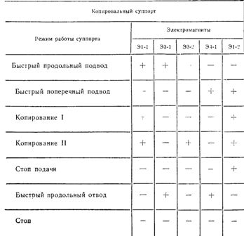
Rice. 2. Cyclogram of operation of hydraulic electric drives
Unlike the tabular method of drawing cyclograms, the graphic method allows to determine the condition not only of hydro- and pneumoelectric and command equipment, but also the condition and operation of all types of mechanisms included in the mechanism, electrical equipment that must be designed . Such cyclograms should be visual, easy to draw and understandable to read, and should also fully characterize the operation of all components of the production mechanism.
In the design, cyclograms «on the way», time cyclograms and sequence diagrams of the sequence of operation of mechanisms are most often used.
The choice of the type of cyclogram is determined by the complexity of the cycle of the designed object.
Cyclograms "on the way" are the simplest, they consider only the technological transitions of various cycles of action of the mechanisms and the placement of the necessary places for designations for command and executive devices. This cyclogram provides an accurate representation of machine performance.
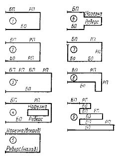
Rice. 3. The simplest diagram of the sequence of the machine tool "on the road": BP — rapid approach: RP — working feed, BO — rapid harvesting, 1 — 9 — technological transitions of the flock.
The cyclogram of work "along the way" of the loading device and the pen allows to assess the progress of parallel processes and the state of the command devices that ensure the start of the work of mechanisms and executive devices that perform the corresponding switches at the loading device.
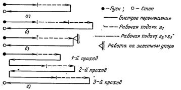
Rice. 4. Diagrams of movement cycles of power heads of modular metal cutting machines.
Explanations of the cyclograms:
The feed head with cutting tools first quickly approaches the workpiece, then the speed of movement decreases and a working feed is obtained. After finishing the processing, the head is quickly returned to its original position (a). When machining bolt holes with a combination tool, first they are drilled (or tapped) with a normal working feed s2, then an automatic transition to a lower feed is performed, in which countersinking is carried out.The cycle diagram of head movements for this case is shown in fig. 4, b.
To counteract the end surfaces near the drilled holes at the end of the working stroke, the tool is rotated without feed — work on a hard stop (Fig. 4, c). The feed head stops by resting on a special screw mounted on a fixed bracket. The oil pressure in the hydraulic system rises and after a time delay determined by the pressure switch setting, the head returns to its original position.
When drilling deep holes, periodically pull the drill bit away from the workpiece to remove chips and cool it. The power head motion cycle corresponding to this case is shown in Fig. 4, d. At the end of the drilling, the head with the tools is returned to its original position.
Complex cycles, in which a large number of electrical devices or machines are involved, are depicted in the form of time cyclograms, which show technological transitions in seconds (or minutes) and the operation of individual units of the production mechanism.
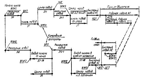
Rice. 5. Cyclogram of work "on the way" of the loading device in the pen of the machine