Types of power supply schemes and their areas of application
 The main problem in low voltage distribution is circuit selection. A properly designed circuit should ensure the reliability of the power supply. electrical receivers in accordance with the degree of their responsibility, high technical and economic indicators and ease of operation of the network.
All circuits encountered in practice are combinations of separate elements — feeders, trunks, and branches, for which we will adopt the following definitions:
feeder — a line designed to transmit electricity from switchgear (panel) to a distribution point, highway or separate electrical receiver;
highway - a line intended for the transmission of electricity to several distribution points or energy consumers connected to it at different points,
branch — outgoing line:
a) from the main line and intended for the transmission of electricity to a distribution point or electrical receiver,
b) from a distribution point (switchboard) and is intended for the transmission of electricity to one electrical receiver or to several small electrical receivers included in the "circuit".
In the future, all feeders, highways and branches from the last to the distribution points will be called a supply network, and all other branches - a distribution network.
One of the main problems solved in the design of shop networks is the choice between main and radial power distribution schemes.
In a backbone power supply scheme, one line — the main line — serves, as indicated, several distribution points or receivers connected to it at its various points, with a radial feed, each line is a beam connecting a network node (substation, distribution point) with one user. In the overall complex of the network, these schemes can be combined.
So that the distribution of stores may be effected by highways, each of which supplies a number of points, from the latter to the receivers, radial lines may diverge.
Typical power supply schemes for industrial plants
The radial diagram shown in Fig. 1, a, is used in cases where there are individual nodes with sufficiently large concentrated loads, in relation to which the substation occupies a more or less central place.
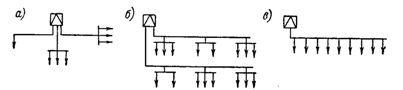
Rice. 1. Diagrams of distribution of electrical energy from substations to electrical receivers: a — radial; b — main line with concentrated loads; c — trunk line with distributed load.
With a radial scheme, individual sufficiently powerful electrical receivers can receive energy directly from the substation, and groups of less powerful and closely spaced electrical receivers — through distribution points installed as close as possible to the geometric center of the load. Low voltage feeders are connected to substations to main switchboards through circuit breakers and fuses or through air circuit breakers.
Radial circuits with direct supply from substations include all supply circuits for high-voltage electrical receivers, either from the high-voltage switchgear in the substation, or directly from the step-down transformer, if the "block transformer - electrical receiver" scheme is adopted.
Trunk power supply schemes apply in the following cases:
a) when the load has a concentrated nature, but its individual nodes are located in the same direction with respect to the substation and at relatively small distances from each other, and the absolute values of the loads of individual nodes are insufficient for rational use of the radial scheme (fig. 1, 6);
b) when the load is distributed with a different degree of uniformity (Fig. 1, c).
In trunk circuits with concentrated loads, the connection of separate groups of electrical receivers, as well as radial circuits, is usually carried out through distribution points.
The task of correctly locating distribution points is of particular importance. The main provisions to be observed in this case are the following:
a) the length of feeders and highways should be minimal, and their route should be convenient and accessible;
b) should be minimized and, if possible, completely exclude the cases of reverse (in relation to the direction of the flow of electricity) feeding of electrical receivers;
c) the distribution points should be located in places convenient for maintenance and at the same time not to interfere with the production work and not to block the paths.
Electric receivers can be connected to distribution points independently of each other, or combined in groups — "chains" (fig. 2 -b).
Rice. 2 Schemes of connection of electrical receivers to distribution points: a — independent connection; b — chain connection.
The daisy-chain is recommended for low-power electrical receivers close to each other, but at a considerable distance from the distribution point, as a result of which significant savings in wire consumption can be achieved. However, in this case, single-phase and three-phase electric consumers must not be connected in one circuit.
In addition, for operational reasons, it is not recommended to connect together:
(a) more than three electrical receivers in total;
b) electric receivers of mechanisms for various technological purposes (for example, electric motors of metal-cutting machines with electric motors of plumbing units).
For distributed loads on the highway, it is recommended that the electrical receivers be connected directly to the highways, and not through the distribution points, as is usual in the schemes discussed above.
Accordingly, the following two main requirements are imposed on load-distributed highways:
a) the laying of highways must be carried out at the lowest possible height, but not lower than 2.2 m from the floor;
b) the design of highways must allow frequent branching of electrical receivers, and when laying in accessible places, exclude the possibility of touching live parts.
Highways made in the form meet these requirements tires in closed metal boxes.
Busbars are generally used in workshops where electrical receivers are arranged in more or less regular rows and where, in addition, frequent movements of equipment are possible. Such workshops include mechanical, mechanical repair, tool and other similar workshops by the nature of the equipment arrangement and environmental conditions.
At concentrated loads, when the number of branches from the network is relatively small, the electrical network must be laid much higher, choosing places where it is possible to fill with bare wires (busbars or conductors) or insulated wires. At the same time, due to the lack of continuous closure, the productivity of the line increases and the whole structure becomes cheaper.
Mains power supply electric lighting, as a rule, is not connected to power feeders and highways, but is carried out by separate networks from the buses of the main switchboards of substations.
In the case of "block transformer - network" schemes, the lighting networks are most often branched off from the main sections of the electrical network. The separation of electrical and lighting networks is caused by the following circumstances:
a) relatively low voltage loss allowed in lighting networks,
b) the ability to switch off the entire supply network while maintaining the lighting supply.
An exception to this general rule is allowed for objects of secondary importance with low loads and irresponsible visual work, as well as for powering emergency lighting.
The choice of the power supply scheme is also significantly influenced by the need to reduce power for electricity consumers of the 1st and 2nd categories.
For electrical receivers of the 1st category, the power supply must be from two independent sources, which may include power transformers if they are connected to different, not interconnected, sections of the high voltage switchgear. In this case, the backup power supply of the electrical receivers must have an automatic switch-on (ATS).
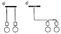
Usually, the most critical installations have spare units in case of failure or preventive repair of working units. The inclusion of reserve units can also be automatic, if necessary according to the conditions of the technological process. An example of automatic mutual reduction of two units is the diagram shown in fig. 3.
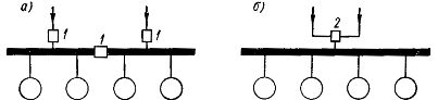
Rice. 3. Power redundancy schemes for low-voltage electricity consumers. 1 — device for manual or automatic switching on and off; 2 — apparatus for manual or automatic switching.
For electrical receivers of the 2nd category, the backup power supply is turned on by the actions of the personnel on duty, but the principles of construction of the circuits remain the same as for the consumers of electricity of the 1st category with the only difference that the second source of power supply may not be independent .
For groups of low-voltage users, it is possible to use two radically different schemes for reducing power, shown in Fig. 3.
According to scheme a, the power consumers are divided into two groups, each of which has a separate power supply, and therefore both power supplies are usually switched on. According to scheme b, the electrical consumers are powered through one of the power supplies, and the other is a backup. In both cases, each feeder must be designed for the total load of the two groups of electrical receivers, but the scheme is preferable, since it has less power loss and greater reliability in operation.
The choice of energy plan is also influenced by the production flow. For example, the electrical receivers of all mechanisms connected to each other through a certain technological dependence must also be combined in terms of normal and backup power.