Parts lists, tables, notes and explanations on electrical diagrams
 List of electrical diagram elements
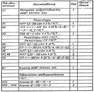
The main characteristics of chain devices are recorded in a list compiled in the form of a table and filled from top to bottom, where the item numbers according to the order specification, designations according to the circuit diagram, name, type, number of devices, technical characteristics and notes are indicated.
The item list includes all equipment and devices on this circuit, as well as electrical equipment borrowed from other projects. At the same time, in a note to the list, it is indicated according to the projects of which organization this equipment was ordered.
Electrical devices and devices in the list are grouped according to the place of installation. Appliances and devices whose contacts are circled in thin lines are not included in the list of this diagram, as they are taken into account in the lists of the corresponding diagrams. An example of designing the item list is shown in the figure.
If the scheme is made on several sheets, then the list of elements is placed on the first sheet. The list of elements can also be done on a separate sheet.
Diagrams and tables of the contacts of electrical devices and devices on the diagrams
Diagrams and tables for switching their contacts are placed on diagrams in which multi-position devices (keys, keys, software devices, etc.) are used.
The tables provide data reflecting the type of device, type of handle (front) and location of contacts (rear), type of handle and package, contact numbers and mode of operation. Pins not used in the circuit are marked with an asterisk (*). The meaning of the asterisk is explained in a note. Above the table, indicate the name and alphanumeric designation apparatus.
For all software devices, limit and travel switches, etc., the diagrams show diagrams of their operation with explanations. If necessary, give cyclograms for equipment operation and equipment.
As an example, FIG. 2 shows a diagram of the operation of the valve limit switches. The diagram shows in which valve positions the contacts are closed or open.
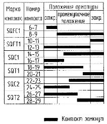
Schematic diagram of the limit switch
The contacts of the devices of this circuit, occupied in other circuits, are depicted in the free field of the drawing in the form of independent circuits separately from the main circuits of the circuit. Above them, as a rule, an explanatory inscription is placed: «Contacts used in other schemes». Near each contact is indicated the short name and number of the circuit, as well as the marking of the circuits of the circuit in which this contact is used.
The contacts of the apparatus used in the circuit, the windings of which are shown in other diagrams, are enclosed in a rectangular loop (thin line). Inside the contour, the reference designation of the contact is indicated, near the contact, and in the note - the number of the circuit in which the coil is shown.
Explanation of process diagrams, diagrams of blocking dependencies of the operation of equipment.
Electrical circuits for controlling complex processes can be supplemented in the drawings with an explanatory diagram and a diagram of the blocking dependencies of the work. In most cases, the explanatory diagram is performed in a simplified form, indicating all units that are part of this technological unit and participate in this circuit diagram. The blocking dependency diagram shows the sequence of operation of the equipment.
Notes and explanations about electrical diagrams
Explanations decipher the purpose and name of each electrical circuit. Explanations are made in the form of tables, which are placed to the right or below the circuit in question, depending on the horizontal or vertical placement of the circuits in the diagram.
In some cases, there may be brief textual explanations of the principle of operation of complex circuits.
Notes to the diagrams contain general information without which it is impossible to establish the interconnection of the materials of the technical documentation.
The notes give:
-
number of specifications ordered for devices and equipment used in this scheme;
-
instructions on the applicability of this scheme to several units;
-
instructions for changing the internal connection schemes of devices (if necessary) and clarifying the characteristics of devices, etc.;
-
other information necessary in a particular case.
When placing several diagrams in one drawing, above each diagram, indicate its purpose.
Applicability tables in electrical circuits
When using the multi-unit scheme, application notes are placed in the applicability table. The table records the names of all units operating according to this scheme and instructions for using the circuit elements of each machine or unit.