Designations of switches and switches on electrical diagrams
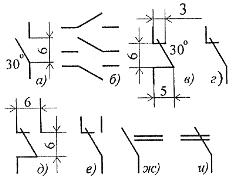
 Conventional graphic symbols of switching products — switches, switches, electromagnetic relays constructed based on the symbols of the contacts: closing (Fig. 1, b), opening (c, d) and switching (d, f). Contacts that simultaneously close or open two circuits are labeled as shown in Fig. 1, (g and i).
For the initial position of the closing contacts of the electric circuits, the open state of the switched-on electric circuit is assumed, the opening contacts are closed, the switching ones are the position in which one of the circuits is closed, the other is open (the exception is the contact with the neutral position). The UGO of all contacts is allowed to be displayed only in mirrored or rotated 90 ° positions.
The UGO standardized system provides reflection of such design features as the simultaneous operation of one or more contacts in the group, the absence or presence of their fixation in one of the positions.
 Rice. 1
Rice. 2
So, if it is necessary to show that the contact closes or opens earlier than others, the symbol of its movable part is supplemented with a short stroke directed to the actuation side (Fig. 2, a, b), and if later, with a blow directed in the opposite direction (Fig. 2, c, d).
The absence of fixation in the closed or open position (self-return) is indicated by a small triangle, the apex of which is directed to the initial position of the movable part of the contact (Fig. 2, e, f), and fixation with a circle on the symbol of its stationary part (Fig. 2, g and).
The last two UGOs of electric circuits are used in cases where it is necessary to show a type of switching product, the contacts of which usually do not have these properties.
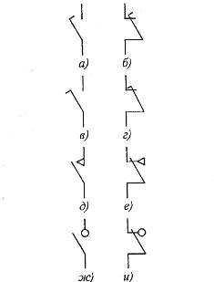
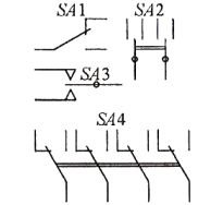
Conventional graphic designation of circuit breakers (Fig. 3) is based on the make and break contact symbols. This means that the contacts are fixed in both positions, that is, they have no self-return.
Rice. 3.
The letter code of products in this group is determined by the circuit involved and the design of the switch. If the latter is placed in a control, signaling, measurement circuit, it is indicated by the Latin letter S, and if in the power circuit - by the letter Q. The control method is reflected in the second letter of the code: buttons, switches and switches are indicated by the letter B (SB), automatic — with the letter F (SF), all others — with the letter A (SA).
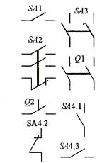
If there are several contacts in the switch, the symbols of their moving parts on the electrical circuits are placed in parallel and connected by a mechanical connection. As an example, FIG.3 shows the conventional graphic designation of the circuit breaker SA2, containing one NC and two NO contacts, and SA3, consisting of two NO contacts, one of which (in the figure - the right one) closes later than the other.
Switches Q1 and Q2 are used to switch power circuits. Contacts Q2 are mechanically connected to each control element as shown by a dashed line segment. When depicting contacts in different parts of the circuit, their belonging to one switching product is traditionally reflected in alphanumeric designation (SA 4.1, SA4.2, SA4.3).
Rice. 4.
Similarly, based on the contact symbol of the switch, the conventional graphic designations of the two-position switches are built on the electrical circuits (Fig. 4, SA1, SA4). If the switch is fixed not only in extreme, but also in medium (neutral) position, the symbol of the moving part of the contact will be interposed between the symbols of the stationary parts, the possibility of rotation in both directions is indicated by a dot (SA2 in Fig. 4). The same is done if it is necessary to show on the diagram a switch that is fixed only in the middle position (see Fig. 4, SA3).
A distinctive feature of UGO buttons and switches is a button symbol connected to the designation of the movable part of the contact by a mechanical connection (Fig. 5). In this case, if the conventional graphic designation is built on the basis of the main contact symbol (see Fig. 1), it means that the switch (switch) is not fixed in the pressed position (when the button is released, it returns to its original position).
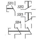
Rice. 5.
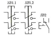
Rice. 6.
If it is necessary to show fixation, use the symbols of the fixation contacts specially designed for this purpose (Fig. 6). The return to the original position when pressing another switch button is indicated in this case by the sign of the locking mechanism attached to the symbol of the moving part of the contact on the side opposite to the symbol of the button (see Fig. 6, SB1.1, SB 1.2). If the return occurs when the button is pressed again, the symbol of the locking mechanism is displayed instead of the mechanical connection (SB2).
Multi-position switches (eg biscuits) mean as shown in fig. 7. Here SA1 (for 6 positions and 1 direction) and SA2 (for 4 positions and 2 directions) are switches with outputs from moving contacts, SA3 (for 3 positions and 3 directions) — without outputs from them. The conventional graphic designation of individual groups of contacts is shown on the diagrams in the same position belonging to the same switch, traditionally shown in the reference designation (see Fig. 7, SA1.1, SA1.2).
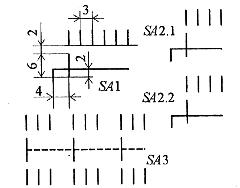
Rice. 7.
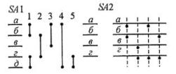 Rice. eight
To display multi-position switches with complex commutation, GOST provides several methods. Two of them are shown in fig. 8. Switch SA1 — for 5 positions (they are indicated by numbers; letters a -d are entered only for explanation). In position 1, chains a and b, d and e are interconnected, in positions 2, 3, 4, chains b and d, a and c, a and e respectively, in position 5 — chains a and b, c and d …
Switch SA2 — 4 positions. In the first of them, the chains a and b are closed (this is indicated by the dots located below them), in the second - chains c and d, in the third - c and d, in the fourth - b and d.
Zorin A. Yu.