Protective relays and electrical circuits
 In the event that networks, enterprises do not require complex devices and automation to protect themselves from emergency and abnormal modes, they use protective devices at alternating operating current with relays with direct and indirect action.
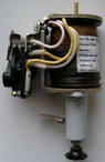
The main direct acting relays include oil switches built into the drives: Instantaneous Overload Relay RTM, Time Delay Overcurrent Relays RTV, Time Delayed Undervoltage Relays RNV, Independent Power Source Solenoid Disconnect, for PP-Drives 61 and PP- 61K, current stop electromagnet for EOTT or TEO chipping circuits. Remote control solenoids (on and off) are installed in all spring drives.
Current relays RTM depending on the version, they have operating current settings from 5 to 200 A. RTV current relays with a time delay of actuation in a current-independent part In NSwithin 0.5 — 4s have the following versions: PTB-I, RTV -II and RTV-II — the independent part of the characteristics starts at a current multiple of 1.2 — 1.7 of the operating current, relay PTV-IV, RTV-V and RTV-VI — with a multiple of 2.5-3.5.The operating current settings of the PTB relay, depending on the version, are from 5 to 35 A.
An important parameter of the PTB relay is the return coefficient Kv, ranging from 0.6 to 0.89, with a higher current coefficient and a shorter delay time, the protection takes a larger Kv value.
In protection schemes with tripping, tripping solenoids TEO-Az with setting 1.5 A and TEO-II with setting 3.5 A in drives PP-61, PP-61K and PP-67, and solenoids EOTT with setting 3, 5 A in the drive PPV-10 and circuit breakers VVM-10 and VMP-10P.
Undervoltage relays with time delay RNV designed to open the circuit breaker when the voltage drops within 35 - 65% of nominal with mandatory tripping below 35%. The relay actuation voltage is not adjustable. The delay can be adjusted from 0.5 to 9 s (VMP-10 breaker actuation relay from 0 to 4 s).
The RNV relay is usually connected directly to the line voltage in the secondary winding of the voltage transformer.
Apply for AC overcurrent protection the RT-85, RT-86 and RT-95 Maximum Current Combination Relays (Indirect Acting).
These relays consist of two main elements: inductive - with a rotating disk, with the help of which a limited time-dependent delay is created, and electromagnetic - instantaneous to perform current interruption. The change-over contact is able to maneuver and unblock a circuit fed by current transformers with secondary currents up to 150 A.
In fig. 1 and 2 shows the most commonly used overcurrent protection schemes in power supply systems - 6 — 10 kV
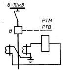
Rice. 1. Protection circuit with one relay connected to the current difference
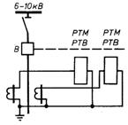
Rice. 2… Protection circuit with two relays connected to phase currents
The first circuit has the least number of current relays and connecting wires. Its disadvantages include: less sensitivity than a two-relay two-phase circuit, since its coefficient Ksx = 1.73 (for a two-relay two-phase circuit Ksh = 1). Damage to the protection in case of failure of a single current relay or wires connecting it to current transformers.
A single-relay circuit is used in distribution networks of 6-10 kV to protect non-critical low-power electric motors and static capacitors, while monitoring the sensitivity of the protection.
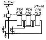
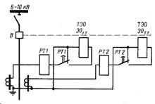
Main protective circuit for power systems of industrial enterprises - two-relay two-phase. Since spring drives have several RTM and PTV overcurrent relays, a number of relay switching schemes can be recommended, shown in Fig. 3, 4.
An example of a connection diagram for an indirect protection relay is shown in fig. 5.
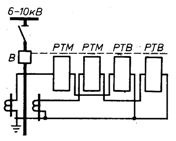
Rice. 3… Protection circuit with RTM and RTV relays connected to phase currents
Rice. 4… Protection circuit with two relays connected to phase currents and one relay connected to differential currents
Rice. 5... Protective circuit with deactivation of switch-off electromagnets
Induction overcurrent relays RT-85, RT-86, RT-95 in the protection circuit with noise reduction have a number of advantages: implementation in a relay for overcurrent protection and overcurrent shutdown, greater sensitivity and accuracy of the performed protection, which allows smaller safety factors for operating current and smaller delay steps overcurrent protection time. To ensure the correct operation of relay protection devices, the error of the current transformer should not exceed 10% by current.
The selection (check) of the current transformers is reduced to determining: initial values - the calculated type of failure, the calculated multiplicity of the current and the calculated secondary load, the permissible external secondary load according to the multiplicity curves with a 10% error, the parameters of the current transformers for a given cross-section of connecting wires or permissible cross-section of connecting wires for given current transformers.
In 6-10 kV networks, earth fault protection acts on the signal, less often on actuation. The common ground fault signal operates from the additional winding of the NTMI type bus voltage transformer.
To determine the 6-10 kV line on which a single-phase earth fault has occurred, turn on the indicator relay in the zero-sequence current transformer circuit or bring the wires from these current transformers to the USZ-ZM central alarm device, on which the short circuit line set by successively pressing the button...
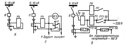
Rice. 6... Protective circuits against earth faults: a, b — for signal, c — for disconnection
In fig. 6, and the switching on of the indicator relay RU-21 is shown, in which a flag drops when this line is grounded. In fig. 6, b shows the activation of the signaling device USZ-ZM.
To turn off in the event of a single-phase ground fault, use the RTZ-50 relay, which is also included in the zero-sequence current transformer circuit (Fig. 6, v). This relay requires a voltage supply from a voltage transformer. Since the relay has weak contacts, the protection circuit requires the use of an intermediate relay.