Electrical schemes of technological control and signaling
 Technological control schemes consist of open channels through which information about the progress of the technological process enters the control point of the object.
Technological control systems have a large number of parameters (or states of production mechanisms) for which only two-position information is sufficient for the normal course of the technological process (the parameter is normal — the parameter is outside the norm, the mechanism is activated — the mechanism is deactivated, etc. ).
These parameters are monitored using alarm circuits. Most often, electrical relay-contact elements with light and sound alarms for parameter deviations are most widely used in these circuits.
Light signaling is carried out using various signal fittings. In this case, the light signal can be reproduced with constant or flashing light, the glow of lamps with an incomplete channel. Sound signaling is carried out, as a rule, by means of bells, beeps and sirens.In some cases, signaling for the activation of protection or automation can be done using a special signal showing flashing relays.
Alarm systems are developed specifically for a given object, so there are always their schemes.
Schematic signaling schemes can be divided into the following groups according to their purpose:
1) position (state) signal circuits — for information on the state of the technological equipment («open» — «closed», «activated» — «disabled», etc.),
2) process alarm circuits providing information on the status of such process parameters as temperature, pressure, flow rate, level, concentration, etc.,
3) command signaling schemes, allowing the transfer of various instructions (orders) from one control point to another using light or sound signals.
According to the principle of action, they are distinguished:
1) alarm circuits with individual removal of the audio signal, characterized by sufficient simplicity and the presence for each signal of a separate key, button or other switching device that allows you to turn off the audio signal.
Such schemes are used to signal the position or status of individual units and are of little use for mass technological signaling, since in them, at the same time as the sound signal, the light signal is usually also turned off,
2) schemes with a central (common) capture of a sound signal without repetition of action, equipped with a single device with which you can turn off the sound signal, while maintaining an individual light signal.The disadvantage of circuits without repeated action of the sound signal is the impossibility of receiving a new sound signal until the contacts of the electrical devices that caused the appearance of the first signal are opened,
3) circuits with central removal of an audio signal with action repetition, which favorably differ from previous schemes in the ability to reissue an audio signal when any alarm sensor is triggered, regardless of the state of all other sensors.
According to the nature of the current, the schemes are divided into direct and alternating current.
In the practice of developing systems for automation of technological processes, various signaling schemes are used, which differ both in structure and in methods of building their individual nodes. The choice of the most rational principle for building an alarm circuit is determined by the specific conditions of its operation, as well as by the technical requirements for light-signal equipment and alarm sensors.
Signal circuits for positioning
These schemes are implemented for mechanisms that have two or more working positions. It is not possible to show and disassemble all the signal circuits encountered in practice, as well as to analyze the reliability and efficiency of each of them due to their diversity. Therefore, below we will consider the most typical and often repeated in practice options for schemes.
The most widespread are two options for building schemes for signaling the position (state) of technological mechanisms:
1) alarm circuits combined with control circuits,
2) alarm circuits with independent power control circuits for a group of technological mechanisms with one or different purposes.
Signal circuits combined with control circuits, as a rule, are carried out when boards and control panels do not have mnemonic circuits, and the useful area of \u200b\u200bthe boards and consoles allows the use of signal fittings without limiting their sizes, which allows direct power supply from control circuits . Signaling of the position (state) of the technological mechanisms in such schemes can be carried out by one or two light signals with uniform burning of the lamps.
Schemes built with one lamp signal, as a rule, for the on state of the mechanism and are used in conditions where the course of the technological process and reliability allow such an alarm.
It should be noted that such schemes do not provide for equipment that allows during operation to periodically check the serviceability of the lamps. The lack of such control in case of burning out of the lamp can lead to incorrect information about the state of the mechanism and disruption of the normal course of the technological process. Therefore, if false information about the state of the technological process is not allowed to appear, circuits with two-lamp signaling are used.
Positioning signaling circuits using two lamps are also used for mechanisms such as closing devices (locks, shock absorbers, valves, shock absorbers, etc.), as they provide reliable signaling of two working positions («Open» — «Closed» ) of such devices using a single lamp is practically difficult.
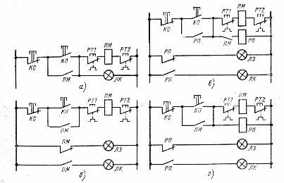
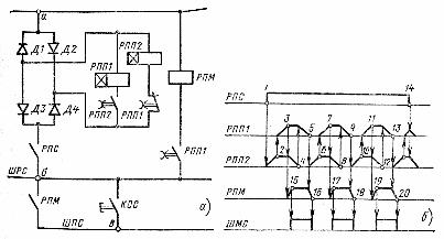
Rice.1... Examples of building the simplest signaling schemes combined with control schemes
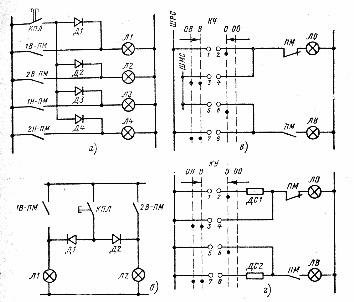
Rice. 2... Examples of signal schemes with independent power supply: a — turning on the lamps through the block contacts of magnetic starters, b — bringing the diagrams into a form that is easy to read, c — if the position of the control switch does not coincide with the position of the controlled mechanism, the lamp flashes, d — if the control key does not match the position of the controlled mechanism, the lamp burns out incompletely, LO — signal lamp «The mechanism is disabled», LV, L1 — L4 — signal lamps "The mechanism is on", V, OV, OO, O — positions of the control key KU (respectively "Enabled", "Enable operation", "Operation disabled", "Disabled"), SHMS - flashing light bus, SHRS - uniform light bus, DS1, DS2 - additional resistors, PM — magnetic starter block contacts, KPL — lamp check button, D1- D4 — separation diodes
Let's summarize some of the results. Schemes with independent power supply control circuits (see Fig. 2) are mainly used to signal the position of various technological mechanisms on the mnemonic diagrams. In such schemes, mainly small-sized signal fittings are used, designed to supply alternating or direct current with a voltage not exceeding 60 V.
The signal can be reproduced using one or two lamps lit with constant or flashing light (see Fig. 2, c) or incomplete heating (see Fig. 2, G). Such light signals are usually used in schemes where it is signaled that the position of the remote control of the mechanism, in this case the KU control key, does not correspond to the actual position of the mechanism.
In signal circuits for a position with power independent of the control circuits performed using one lamp, as a rule, equipment is provided for monitoring the serviceability of the signal lamps (see Fig. 2, a).
Process signaling schemes
Process signaling circuits are designed to alert service personnel to a violation of the normal course of the technological process. Technological signaling is reproduced with a constant and flashing light and, as a rule, is accompanied by an audible signal.
Signaling by purpose can be warning and emergency. This division provides a different response of the operating personnel to the nature of the signal, which determines one or another degree of disruption of the technological process.
The largest application is found in technological signal circuits with a central pickup of an audio signal. They make it possible to receive a new sound signal before opening the contacts that caused the appearance of the previous signal. The use of different relay and signaling equipment, different voltages and types of current practically does not change the principle of operation of the circuits.
Technological processes require positional control of a large number of parameters, and a characteristic feature of technological signal chains is the presence of common nodal circuits in which information from many two-position technological sensors is processed.
Information from these nodes is issued in the form of sound and light signals only for those parameters whose values are outside the norm or are necessary to control the technological process. Shared nodes reduce the need for hardware and the cost of automating production.
Depending on the number of parameters to be signalled, the light signaling can be done with a constant or flashing light. When signaling many parameters (more than 30), schemes with a flashing signal are used. If the number of parameters is less than 30, uniform light schemes are used.
The algorithm of operation of technological signaling circuits in most cases is the same: when the parameter deviates from the set value or is exceeded, sound and light signals are given, the sound signal is removed by the button to remove the sound signal, the light signal disappears when the deviation of the parameter from the permissible value decreases.
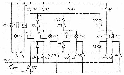
Rice. 3... Process signaling circuit with separation diodes and flashing light: LCN — voltage control lamp, Зv — buzzer, RPS — warning alarm relay, RP1 -RPn — intermediate relays of individual signals switched on via sensor contacts D1 — Dn on technological control, LS1 — LSn — individual lamps, 1D1-1Dn, 2D1-2Dn — isolating diodes, KOS — button for testing the signal, KSS — button for receiving a signal, SHRS — steady light bus, SHMS — flashing light bus
Rice. 4. Alarm circuit using a pulse pair instead of a flashing light source
Process alarm circuits with a dependent audible signal from a light signal are only used for warning signaling of the status of non-critical process parameters, since in these circuits a loss of signal is possible if the signal lamp is defective.
It is possible to encounter process signaling schemes with individual sound signal pickup.Circuits are constructed using an independent switch, button, or other switching device for each signal that turns off the beeper, and are used to signal the status of the individual units. Simultaneously with the sound signal, the light signal is also switched off.
Command signal schemes
Command signaling provides one-way or two-way transmission of various command signals in conditions where the use of other types of communication is technically impractical, and in some cases difficult or impossible. Command signaling schemes are simple and usually easy to read.
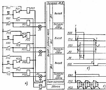
Rice. 5. Example of a command signaling schematic circuit diagram (a) and interaction diagram (b and c).
In fig. 5, and a diagram of a one-way light and sound signal for calling commissioning personnel to jobs is shown. The call is made from the workplace by pressing the call buttons (KV1-KVZ), which on the dispatcher's panel include the light (L1-ЛЗ) and sound (Sound) signals. The dispatcher, after establishing the number of the workplace through the light signal, from which the signal was received, by pressing the signal removal button, the KCC returns the circuit to its original state. Relays RP1-RPZ and RS1-RSZ are intermediate.