Automation of pumps and pumping stations
Automation of pumping units makes it possible to increase the reliability and continuity of water supply, reduce labor and operation costs, as well as the size of control tanks.
For automation of pumping units, with the exception of general purpose equipment (contactors, magnetic starters, switches, intermediate relays), special control and monitoring devices are used, for example, level control relay, centrifugal pump fill control relays, jet relay, float switches, electrode level switches, various pressure gauges, capacitive sensors, etc.
Control station — a complete device up to 1 kV, designed for remote control of electrical installations or their parts with automated performance of control, regulation, protection and signaling functions. Structurally, the control station is a block, panel, cabinet, board.
Control unit — a control station, all elements of which are mounted on a separate plate or frame.
Control panel — a control station, all elements of which are mounted on boards, rails or other structural elements assembled on a common frame or metal sheet.
Control panel (ShTSU control station shield) It is an assembly of several panels or blocks on a three-dimensional frame.
Control cabinet - a control station protected from all sides in such a way that when doors and covers are closed, access to live parts is excluded.
Automation of pumps and pumping stations, as a rule, comes down to controlling the submersible electric pump from the water level in the tank or the pressure in the pressure pipeline.
Let's look at examples of automation of pumping units.
In fig. 1, and shows an automation scheme of the simplest pump unit — drainage pump 1, and in fig. 1, b shows the circuit diagram of this installation. Automation of the pumping unit is carried out using a floating level switch. The KU control key has two positions: for manual and automatic control.
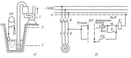
Rice. 1. The design of the drainage pumping device (a) and its electrical circuit for automation (b)
In fig. 2 transmission automation scheme for controlling a submersible pump according to the water level in the tank of a water tower, implemented on relay-contact elements.
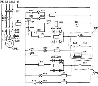
Rice. 2. Schematic diagram of automation from a submersible pump according to the water level in the tank-water tower
The operation mode of the automation circuit from the pump is set by the CA1 switch. When you set it to the "A" position and turn the QF switch on, voltage is applied to the control circuit.If the water level in the pressure tank is below the electrode of the lower level of the remote control sensor, then the contacts SL1 and SL2 in the circuit are open, the relay KV1 is turned off, and its contacts in the circuit of the coil of the magnetic starter KM are closed. In this case, the magnetic starter will turn on the pump motor, at the same time the signal lamp H will go out L1 and the lamp H will light up L2. The pump will supply water to the tank under pressure.
When water fills the space between the SL2 lower level electrode and the sensor body connected to the neutral wire, the SL2 circuit will close, but the KV1 relay will not turn on because its pins in series with SL2 are open.
When the water reaches the electrode of the highest level, the SL1 circuit will close, the KV1 relay will turn on and, having opened its contacts in the circuit of the coil of the magnetic starter KM, will turn off the latter, and after closing the closing contacts, it will be energized alone via the SL2 sensor circuit. The pump motor will turn off and the warning lamp H will go out.L2 and the lamp H will light up L1. The pump motor will turn on again when the water level drops to the position when the circuit SL2 is open and relay KV1 will be deactivated.
Turning on the pump in any mode is possible only if the DSX dry run sensor circuit is closed (SL3), which controls the water level in the well.
The main disadvantage of the level control is the susceptibility of the electrodes of the level sensors to freeze in winter, due to which the pump does not turn off and the water overflows from the tank. There are cases of the destruction of water towers due to the freezing of a large mass of ice on their surface.
When controlling the operation of the pump by pressure, an electrical contact pressure gauge or pressure switch can be installed on the pressure line in the pump room. This facilitates sensor maintenance and eliminates exposure to low temperatures.
In fig. 3 transmissions circuit diagram of the control of a water supply (pumping) installation of a tower according to the signals of an electric contact manometer (according to the pressure).
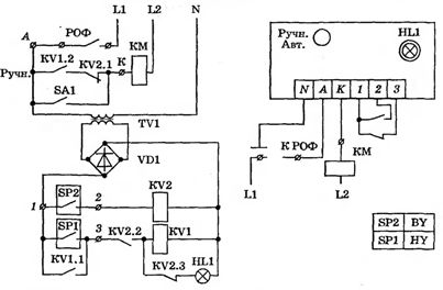
Rice. 3. Schematic diagram of the control of a water installation on a tower by an electrical contact manometer
If there is no water in the tank, the contact of the pressure gauge СП1 (lower level) is closed, and the contact СП2 (upper level) is open. Relay KV1 works, closing contacts KV1.1 and KV1.2, as a result of which the magnetic starter KM turns on, which connects the electric pump to a three-phase network (power circuits are not shown in the diagram).
The pump supplies water to the tank, the pressure rises until the manometer contact closes, СП2 set to the upper water level. After closing contact СP2, relay K is activated V2, which opens contacts KV2.2 in the circuit of the coil of the relay KV1 and KV2.1 in the circuit of the coil of the magnetic starter KM; the pump motor turns off.
When water flows out of the tank, the pressure decreases, СP2 opens, cutting off KV2, but the pump does not turn on, since the pressure gauge is in contact, СP1 is open and the relay coil KV1 is turned off. The pump turns on when the water level in the tank drops before the pressure gauge contact closes. СП1.
The control circuits are powered by a 12 V step-down transformer, which increases safety when servicing the control circuit and the electrical contact pressure gauge.
To ensure the operation of the pump in the event of a malfunction of the electrical contact pressure gauge or control circuit, a switch CA1 is designed. When it is turned on, the control contacts KV1.2, KV2.1 are manipulated and the coil of the magnetic starter KM is directly connected to the 380 V network.
In the phase gap L1, the control circuit includes a contact ROF (loss of phase relay), which opens in the event of an open phase or asymmetric mode of the supply network. In this case, the circuit of the coil KM is broken and the pump is automatically switched off until the fault is rectified.
The protection of the power circuits in this circuit from overload and short circuit is carried out by an automatic switch.
In fig. 4 transmission scheme for the automation of a water pumping installation, which contains an electric pump unit 7 of a submersible type, located in a well 6. A check valve 5 and a flow meter 4 are installed in the pressure pipeline.
The pump unit has a pressure tank 1 (water tower or air-water boiler) and Pressure sensors (or level) 2, 3, with sensor 2 responding to the upper pressure (level) in the tank and sensor 3 to the lower pressure (level) in the tank. The pumping station is controlled by the control unit 8.
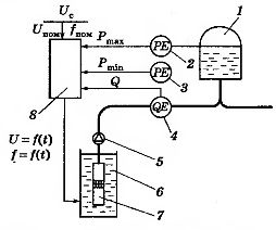
Rice. 4. Scheme for the automation of a water pumping device with a variable frequency
The pump unit is controlled as follows. Suppose that the pump unit is turned off and the pressure in the pressure tank decreases and becomes lower than Pmin... In this case, a signal is sent from the sensor to turn on the electric pump. It starts by gradually increasing the frequency. is current supplying the electric motor of the pumping unit.
When the speed of the pump unit reaches the set value, the pump will enter the operating mode. By programming the operating mode frequency converter you can ensure the necessary intensity of the pump's work, its smooth start and stop.
The use of an adjustable electric drive of a submersible pump makes it possible to implement direct flow water supply systems with automatic pressure maintenance in the water supply network.
The control station, which ensures a smooth start and stop of the electric pump, automatic maintenance of pressure in the pipeline, contains a frequency converter A1, a pressure sensor BP1, an electronic relay A2, a control circuit and auxiliary elements that increase the reliability of electronic equipment (Fig. 5 ).
The pump control circuit and frequency converter provide the following functions:
— smooth start and stop of the pump;
— automatic control by level or pressure;
— protection against "running dry";
— automatic shutdown of the electric pump in case of incomplete phase mode, unacceptable voltage drop, in the event of an emergency in the water supply network;
— overvoltage protection at the input of frequency converter A1;
— signaling for switching on and off the pump, as well as for emergency modes;
— heating of the control cabinet at negative temperatures in the pump room.
Soft start and soft deceleration of the pump is done using frequency converter type A1 FR-E-5.5k-540ES.
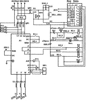
Rice. 5. Schematic diagram of automation of a submersible pump with a device for soft start and automatic pressure maintenance
The submersible pump motor is connected to the U, V and W terminals of the frequency converter. When the button СB2 is pressed Relay «Start» K1 is activated, whose contact K1.1 connects the inputs STF and computer of the frequency converter, ensuring smooth start of the electric pump according to the program specified when setting the frequency converter.
In the event of a fault in the frequency converter or the pump motor circuits, the AC converter circuit is closed, ensuring the operation of relay K2. After actuation of K2, its contacts K2.1, K2.2 close and contact K2.1 in the circuit K1 opens. The output of the frequency converter and relay K2 is switched off. Reactivation of the circuit is possible only after the fault has been removed and the protection has been reset with the 8V3.1 button.
Pressure sensor BP1 with analog output 4 … 20 mA is connected to the analog input of the frequency converter (pins 4, 5), providing negative feedback in the pressure stabilization system.
The functioning of the stabilization system is ensured by the PID controller of the frequency converter. The required pressure is set by potentiometer K1 or by the control panel of the frequency converter. When the pump is running dry, contact 7-8 of the electronic resistance relay A2 closes in the coil of the short-circuit relay, and the dry-running sensor is connected to its contacts 3-4.
After the short-circuit relay is activated, its contacts K3.1 and short-circuit.2 are closed, as a result of which the protective relay K2 is activated, which ensures that the pump motor is turned off. In this case, the short-circuit relay is powered independently through contact K3.1.
In all emergency modes, the HL1 lamp lights up; the HL2 lamp lights up when the water level is unacceptably low (with «dry operation» of the pump). The heating of the control cabinet in the cold season is carried out with the help of electric heaters EK1 … EK4, which are switched on by the contactor KM1 when the the thermal relay VK1. Protection of the input circuits of the frequency converter from short circuit and overload is carried out by the breaker QF1.
Rice. 5. Automation of the pumping unit
The article uses materials from the book Daineko V.A. Electrical equipment of agricultural enterprises.
See also: A simple automated control scheme for two waste pumps