Single-phase bridge rectifier circuit
Rectification is considered here as the process of converting alternating current into direct current by means of electrical elements that conduct current predominantly or exclusively in one direction. Such items— semiconductor diodes — represent low resistance when current flows in one direction; very large — when the current flows in the opposite direction.
An ideal rectifier has zero resistance in the forward direction and infinite resistance in the reverse direction and is a switch that opens and closes a circuit when the voltage polarity changes.
In a single-phase bridge circuit, a source of alternating voltage (secondary winding of the transformer) is connected to one of the diagonals of the bridge, and the load is connected to the other.
In the bridge circuit, the diodes work in pairs: during half the period of the mains voltage, the current flows from the secondary winding of the transformer along the circuit VD1, RH, VD2, and during the second half-period - along the circuit VD3, RH, VD4, and in each half-cycle the current flows through the load in one direction, which ensures straightening.The switching of diodes occurs at the moments when the alternating voltage crosses zero.
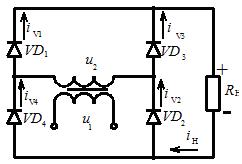 Fig. 1. Single-phase bridge rectifier circuit
The timing diagrams for the bridge circuit are shown in Figure 2.
In a bridge circuit, in each half-cycle, current flows simultaneously through two diodes (for example, VD1, VD2), so the time dependences of currents and voltages will belong to pairs of valves. Average rectifier output voltage
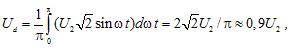
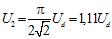
where is u2 the effective value of the AC voltage at the input of the rectifier.
The effective value of alternating voltage (current) is the value of constant voltage (current) developing in a given active resistance the same power as the considered value of alternating voltage (current).
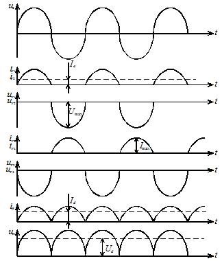 Rice. 2. Timing diagrams of operation of a single-phase bridge rectifier circuit: u2 — curve of the alternating voltage at the input; iV1, iV2 — current curve of diodes VD1 and VD2; uV1, uV2 — voltage of diodes VD1 and VD2; iV3, iV4 — current curve of diodes VD3 and VD4; uV3, uV4 — voltage of diodes VD3 and VD4; in — load current curve; un — load voltage curve
RMS voltage at the rectifier input
The average value of the current through the diode is half the average value of the load current Id:

The maximum value of the current flowing through the diode

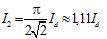
RMS current value of the diode

RMS value of alternating current at the input of the rectifier
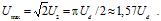
Maximum diode reverse voltage in the non-conducting part of the period
The load voltage consists of the half-sinusoidal transformer secondary voltage followed one after the other.After Fourier expansion, a voltage of this form can be represented in the form

The amplitude of the fundamental harmonic of the rectified voltage with frequency 2?

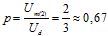
hence, the ripple factor of the rectified voltage
Transformer transformation ratio

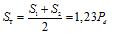
Power of the primary and secondary windings of the valve transformer
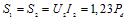
Rated power of the transformer
The disadvantages of a single-phase bridge circuit can be noted: a larger number of diodes and the flow of current in each half-cycle through two diodes at the same time. The latter property of single-phase bridge rectifiers reduces their efficiency due to the increased voltage drop across the semiconductor valve structures. This is especially noticeable in low-voltage rectifiers operating at high currents.
Despite the noted disadvantages, the bridge circuit of the rectifier is widely used in practice in single-phase rectifiers of different power.