What is a flowchart
 The structure diagram is developed in the initial stages of design and precedes development other types of schemes… The structure diagram defines the main functional parts of the product, their purpose and the relationship between them. The diagram shows the principle of operation of the product in its most general form.
The actual arrangement of the component parts of the structure diagram is not taken into account and the method of communication is not disclosed. The circuit construction should give a visual representation of the
- the composition of the product,
- the sequence of interaction of functional parts in the product. Functional parts of the diagram are depicted in the form of rectangles or conventional graphic symbols. When functional parts are depicted as rectangles, their names, types, and designations are written inside the rectangles.
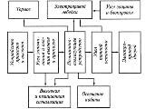
The direction of flow of the process occurring in the product is indicated by arrows connecting the functional parts. In simple product diagrams, the functional parts are arranged in a chain according to the flow of the work process in the direction from left to right.It is recommended to draw diagrams containing several main working channels in the form of parallel horizontal lines.
Below, several examples show the rules and characteristics of building diagrams of devices and systems.
Figure 1 shows a block diagram of an automatic heating and hot water (DHW) system for a building.
The system contains the following functional parts:
1. the unit for measuring thermal energy, with the help of which the amount of consumed thermal energy and the consumption of hot water is determined,
2. heating control system designed to maintain the set temperature and pressure of the heat carrier (water) in the heating circuit, the set air temperature in the premises of the building.
3. HWS control system designed to maintain the required hot water temperature and pressure,
4. power system for all units of the automatic control system,
5. personal computer.
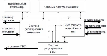
Rice. 1. Block diagram of the automatic heat supply and hot water control system
A feature of this scheme is that. that it shows not only the connections between the individual blocks of the control system, but also the direction of flow of coolant and hot water.
With a large number of functional parts in the product, the elements of the structure diagram can be indicated by serial numbers. At the same time, a list of these functional parts must be compiled. In this case, the clarity of the structure diagram deteriorates, because the role of each functional part is clarified not only from the image, but also with the help of the list.
For an example of the implementation of this option, fig.2 shows a block diagram of the system for stabilizing the rotation speed of the electric motor.
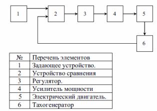
Rice. 2. Block diagram of the system for stabilizing the rotation speed of the electric motor
For complex products consisting of several functional parts, their structural diagrams can also be developed for each part.
For example, in fig. 3 shows a block diagram of the main converter of an electromagnetic flow meter, which is part of the unit for measuring heat energy (Fig. 1) and is designed to determine the current and total flow rate of the coolant (water) passing through a pipeline for a heating circuit.
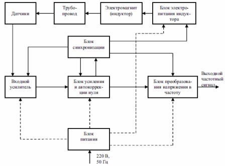
Rice. 3. Block diagram of an electromagnetic flowmeter converter
On the structural diagram, it is allowed to indicate the characteristics of functional parts, explanatory inscriptions and diagrams that determine the sequence of processes in time, as well as parameters at characteristic points (values of currents, voltages, shape and magnitude of pulses, etc.). The data is placed next to the graphic designation or in the free field of the diagram. After the design is completed, the structural diagram of the product is included in the operating documentation for general familiarization of the operating personnel with the product.
Edemski S.N.
White Papers for Industrial Electrical Equipment Manufacturers:
Characteristics of the structure of the cogeneration system
Diesel generators: what they are
Voltaire cardan is your faithful companion
Typical and individual electrical project: which one to prefer?