What is a function chart
 The functional diagram aims to explain the processes taking place in individual functional chains of the product or the product as a whole. For a complex product, several function diagrams are developed to explain the processes occurring under different intended modes of operation. The number of functional diagrams developed for the product, the degree of their detailing and the amount of information placed are determined by the developer, taking into account the characteristics of the product.
The diagram shows the functional parts of the product (elements, devices, functional groups) and the connections between them. The graphic construction of the chain should clearly reflect the sequence of functional processes taking place in the product. The actual arrangement of elements and devices in the product may not be taken into account.
The functional parts and the connections between them are depicted in the form of conventional graphic designations established in the relevant standards for conventional graphic designations of these groups and elements. In this case, the rules for applying schematic diagrams apply.Individual functional parts of the diagram can be depicted in the form of rectangles. In this case, these parts of the diagram should be followed according to the rules of structure diagrams.
According to the functional diagram, indicate:
— for functional groups — the designation assigned to the schematic diagram or the name (if the functional group is depicted as a conventional graphic designation, then its name is not indicated),
— for each device and item depicted conventional graphic symbols — alphanumeric designation indicated on the schematic diagram, its type,
— for each device shown with a rectangle — the reference designation assigned to it on the schematic diagram, its name and the type or designation of the document on the basis of which that device is applied. The document designation is also indicated for the device depicted as a conventional graphic designation. It is recommended to write the names, types and designations of functional parts depicted with rectangles inside the rectangles. Abbreviated or conventional names should be explained in the chart box.
The functional diagram shows the technical characteristics of the functional parts, the parameters in characteristic points, the explanatory inscriptions, etc. If necessary, the diagram shows electrical circuits in accordance with GOST 2.709-72.
If the product includes elements of different types, then it is recommended to develop several schemes of the corresponding types of the same type or one combined scheme containing elements and connections of different types.
On the functional diagram of an electromagnetic flowmeter (Fig. 1) in comparison with it structure diagram (Fig. 3) discloses the content of the principle for measuring the flow rate of a liquid flowing through a pipeline. The remaining circuit elements are shown as rectangles, as in the block diagram.
The diagram shows the formation of an electromagnetic field using electromagnets (inductors) L1 and L2 installed on the pipeline. The principle of installation of sensors B1 and B2 is shown, which measure the emf induced in a conductive liquid flowing in the pipeline and proportional to the flow rate of this liquid. The need to ground the pipeline is also indicated.
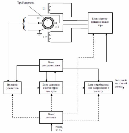
Rice. 1. Functional diagram of an electromagnetic flow meter
Edemski S.N.