Ways to represent elements on electrical circuits
 In electrical circuits element graphic legend (devices, electrical devices) can be represented both by combination and by interval.
A combined way to display elements on charts
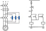
All parts of any device, electrical apparatus are located in close proximity and are usually enclosed in a rectangular, square or circular contour made with a solid thin line (Fig. 1, a). The combined image method is mainly found in power circuits for devices of automation systems and other simple cases.
Aligned images are always used in electrical circuits, for example, as shown in Fig. 1c, which shows a single coil relay with two switching and one pulse contact. Relay outputs are numbered by the manufacturer, their numbers 1-10 are enclosed in circles. Switching contacts are connected to pins 1, 3, 5 and 2, 4, 6, pulse contact is connected to pins 9 and 10.
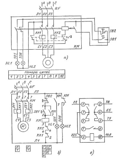
Rice. 1. Scheme made by combined (a) and interval (b) methods.An example of a relay image (c) in a combined way
Expanded view of elements in charts
It is mainly used in electrical diagrams, because with this method the electrical circuits are clearly visible, which greatly facilitates the reading of the diagrams. This is easy to verify by looking at fig. 1b, which shows the same circuit as in fig. 11, a.
With the distributed method, the conventional graphic designations of the components of the devices, the devices are located in different places, but in such a way that the individual circuits are depicted most clearly. The affiliation of the shown contacts, coils and other parts to the same device is established by reference designationsplaced near images of all parts of the same apparatus. So, in fig. 1, b near the contacts of the magnetic starter (power and auxiliary), as well as near the image of the coil, KM is written. Another example: according to the same reference designations KK1 (KK2) it is easy to establish the belonging of contacts and coils thermal relays.
Let us use fig. 1b to illustrate a very convenient technique that facilitates orientation in schematics made in a distributed fashion. This technique is used by a number of design organizations. It is as follows:
1. Circuits are numbered in the diagram. In this example, the locations of the possible circuits (lines) are numbered 1 - 10.
2. A plate is placed under the image of each coil. In column D the plates show the numbers of the circuits in which the main contacts are introduced, in column 3 the numbers of the circuits in which the contact contacts are introduced, and in column P the breaking contacts.The number of cells in the plate is equal to the number of contacts on the device, so it can be used to determine which circuits to search.
3. On the diagram, near the reference designations, indicate on the image of the contact the number of the circuit in which the corresponding coil is included. In the example under consideration, three plates are shown, which are placed under the image of coils KK1, KK2 and KM. In the plate under KK1 (KK2) there are no columns G and Z, since thermal relays have neither main nor closing contacts, and column P reads 7. And indeed, contacts KK1 and KK2 are entered in circuit 7.
In the plate under the coil KM in column D there are numbers 2, 3 and 4. This suggests that the magnetic starter with its main contacts interrupts the supply circuits 2, 3 and 4. In column 3 there are two addresses: 8 and 9, in column P — address 10 and one free tap hole. This means that the starter has two NO and two NC contacts, one NC contact is free.
Schematic diagrams often show devices (devices, regulators, etc.) that have their own circuits. In this case, on a schematic circuit diagram, these devices are depicted in a simplified way (only the input and output circuits and the supply circuits of the supply voltage are shown), and a detailed idea of \u200b\u200bthe principle of operation of the installation is given by the set of its circuit diagram and circuit diagram on the devices.
In the basic electrical diagrams, the conventional graphic designations of the components of the electrical devices involved in a circuit are depicted consecutively one after the other in a straight line, and the individual circuits — one below the other, until parallel lines are formed (execution of the circuit by line). Vertical alignment of lines is allowed.
Communication lines between devices are shown in full, but in some cases, in order not to blur the circuit, they may be interrupted. In this case, line breaks end with arrows. The main (power) circuits of the circuits are implemented in a multi-line image. In a single-line drawing, these schematics are shown when shown for explanation. The main electrical circuits for control, regulation, signaling and power supply are always implemented in a multi-line image.
Start position of devices. The contacts of automatic machines, switches, buttons, relays and other switching devices on the diagrams are depicted in the absence of current in all circuits of the circuit, that is, on the assumption that there is no current in the coils of relays, contactors, magnetic starters, etc., or is so small that the armature cannot be attracted (a typical example is the current in the overload relay coil under normal load) and external forcing forces do not act on buttons, switches, relay armatures, etc. Therefore, all contacts in the diagrams are shown as open and all broken contacts as closed.
If an exception is made to this rule in necessary cases, ie. if individual devices are shown in the selected operating mode, a corresponding explanation is given in the diagram.Devices that do not have a disabled position are rendered in the default position. The contacts of switching devices with two initial positions (for example, a two-position override relay) are shown in one arbitrarily chosen position, which is explained in the diagram. Diagrams of multi-position switches, such as control circuit switches, are supplemented with switching diagrams.