Electrical power circuits for automation systems
 Power supplies for electrical equipment and automation systems are workshop distribution substations, switchboards and power supply units of the power supply systems of the facility being automated, to which no sharply variable load (high-power electric motors, etc.) is connected. The voltage, type of current, and control and protection equipment are, as a rule, connected and coordinated with the power system.
The reliability of the power supply of electrical equipment and electrical receivers of the automation system is assumed to be no less than the reliability of the power supply of the automated facility. The question of the need for curtailment is decided depending on the belonging of electricity consumers to the relevant category of reliability according to PUE, taking into account the availability of reserves in the power supply system of the facility.
A power supply system usually consists of a supply and distribution network.In general, the power supply system can be represented in the form of a diagram shown in fig. 1.
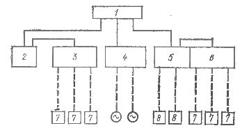
Rice. 1. Scheme and main power supply devices of the automation system: 1 — power supply, 2 — power supply board No. 1, 3 — measurement board No. 1, 4 — valve power supply device, 5 — power supply board No. 2, 6 — measurement board No. 2, 7 — sensors of primary devices, etc., 8 — independent devices.
The power network (solid lines) connects the power supplies of the automated object to the panels and power nodes of the automation system. The distribution network (dotted lines) connects the circuit boards and power units of the automation system to its individual power consumers.
Depending on the relative position of the boards (nodes) of the power supply of the automation system and power sources, as well as the requirements for redundancy of the power circuit, they can be: radial with one-sided (Fig. 2, a) or two-sided (Fig. 2.6) power supply, rack with one-sided (Fig. 2, d) or two-sided power supply from one (Fig. 2, e) or two (Fig. 2, f) independent radial-barrel sources (Fig. 2, c).
If the shields and power nodes 2 are placed in different directions from the power sources 1 and the distance between the shields is greater than from the source to the shields, then power circuits are used. In this case, the shields (nodes) can be powered by one line from one source or two from two independent sources.
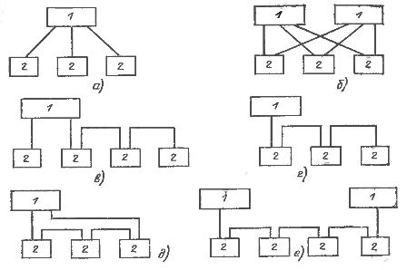
Rice. 2. Scheme of the power supply network of the power supply system
Main power circuits are used when the distance between shields and nodes is much less than to the power source. Power according to mains circuits can be provided from one or two independent sources. Single-source power can only be powered by shields that allow power interruption.
Distribution networks are usually radial, that is, each electrical receiver is connected to the corresponding panel or terminal node with a separate radial line.
The main power supply schemes for the supply and distribution network are performed separately, but if the scheme of the distribution network consists of a small number of groups of power supplies, then it can be combined in one drawing with the diagram of the supply network.
The equipment for controlling power and distribution networks ensures the inclusion and shutdown of electrical receivers and network sections during normal operation, reliable disconnection of electrical receivers and network sections for revisions and repairs, protection against all types of short circuits, as well as overloading (if necessary) .
In order to read power supply diagrams, it is useful to know that the following combinations of control and protection devices can be used in power supply and distribution networks: in power lines — a circuit breaker or a fuse. They are installed at the points of connection to the power supply , as well as at the entrances to the shields and power units.
In power and distribution networks, pack switches, circuit breakers, control switches and toggle switches can be used. It should be noted that:
— control and protection devices are not installed in the circuits of electrical receivers with built-in switches and fuses;
— in the circuits of electric receivers with a built-in fuse, only the control device is provided;
— the installation of control and protection devices in grounding wires of all types is prohibited; in neutral conductors, including when used as grounding conductors, control devices can be installed only if they disconnect all phase conductors;
— in the supply circuits of interconnected devices (for example, a sensor and a secondary device, etc.), the individual elements of which do not work independently of each other, common control and protection devices are installed. In this case, separate switches are provided on the branches to the individual elements of the regulators (for example, the regulating device with remote control);
— in the schemes of step-down transformers with a branched secondary network, the control and protection devices are installed on the side of the primary and secondary voltage windings in each connection of an electrical receiver that does not have a control and protection device. In case of connection on the side of the secondary voltage of an electrical receiver, the control and protection devices in this circuit may not be installed.
For critical, large and complex automation systems, voltage control is provided on the busbars of the power distribution board, switchboards and control boards, etc. Bus voltage control is usually done using signal lamps connected directly to the controlled buses.In some cases, not only the presence of voltage, but also its value is monitored using a voltmeter or voltage relay. The voltage relay includes a light or sound alarm when it is disconnected from the upper or lower permissible value.
The power circuit is performed, as a rule, in a single-line image. The diagram shows the control and protection devices mounted on both the power source side and the automation system power boards side, and the electrical communication lines between them. The images of power supply circuit control and protection devices show: the alphanumeric designation and type of the device, the rated voltage and current, and for protection devices, also the current of the fuse or circuit breaker.
Power management and protection equipment on the power supply side is usually considered in power supply schemes. Devices for the control and protection of the power network on the side of the power panels are taken into account in the automation schemes and are listed in the equipment list of the distribution network schemes.
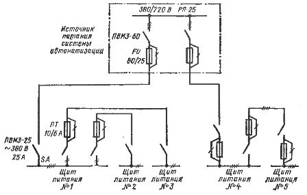
Rice. 3. Scheme of the power network of the automation system, made in a single-line image (only typical labels are given on the diagram).
The distribution network diagram is executed in a multi-line image for each switchboard and power supply unit separately.It shows control devices (knife switches, switches, switches), protective devices (circuit breakers, fuses), converters (rectifiers, transformers, stabilizers, etc.), lighting lamps, contacts, automatic transfer switches (ATS) and electrical connection between device lines.
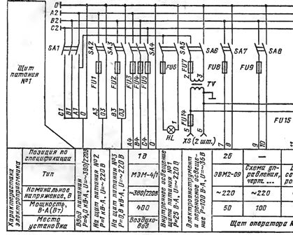
Rice. 4. Scheme of the distribution network of the switchboard No. 1, made in a multi-line image.
Alphanumeric designations are indicated for the images of devices, for transformers — higher and lower voltage, for rectifiers and stabilizers — the type of current, higher and lower voltage. The technical characteristics of switches, switches, circuit breakers and fuses are not indicated on the distribution network diagrams, as they are given in the lists of items of electrical equipment.