Motor control circuits as a function of time
 This type of control is used when all the switching in the electrical circuit of the electric motor takes place at certain moments of time, for example, when automating the process of starting electric motors without monitoring the speed or current. The duration of the intervals is determined and can be adjusted by the time relay settings.
Time control received the greatest spread in the industry due to the simplicity and reliability of mass production electromagnetic and electronic time relays.
So, from fig. 1, a and b, it can be seen that by closing the contact K of the line contactor, the entire resistance of the rheostat is included in the armature circuit, equal to R1 + R2 + R3, and the inclusion of the starting resistance sections can occur at certain time intervals t1, t2 and t3 at certain engine speeds n1, n2, n3 and when the inrush current drops to the set value I2. The time intervals are chosen so that with each subsequent short circuit of the resistance, the motor current does not exceed the permissible I1.
As the motor accelerates from n = 0 to n1, the current decreases to I2 as a result of an increase in the rear electromotive force. After a time interval t1, contact K1 closes, shunting resistance R1, which leads to a decrease in the resistance of the rheostat to R2 + R3, a new increase in current to I1, etc. At the end of the start, the motor accelerates to the rated speed, the starting rheostat is completely removed.
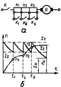
Rice. 1. Motor control circuits as a function of time: a — DC motor starting rheostat, b — starting diagram
Consider some motor control circuits as a function of time.
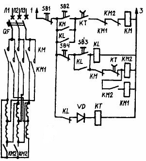
In time-dependent control of an induction motor with a wound rotor (Fig. 2), the time delay required to short-circuit individual steps of the starting rheostat is provided by pendulum time relays, the number of which is equal to the number of steps. The scheme works as follows.
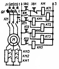
Rice. 2. Control circuit as a function of time of a wound-rotor induction motor
When you click on button SB1 receives power to the contactor coil on the KM line, which connects the motor stator to the mains. At the same time, the output rheostat is fully introduced. Together with the contactor, the time relay KT1 is turned on, which after a certain time interval closes the contact in the circuit of the coil of the contactor KM1.
The contactor operates and closes the first section of the rheostat to start the rotor. At the same time, the time relay KT2 turns on, which closes its contacts with a delay and turns on the coil KM2 and the time relay KTZ. The contacts of the contactor KM2 short circuit the second stage KM2 of the starting rheostat.In addition, with a time delay, the contact of the KTZ relay is triggered, turning on the KMZ winding, which makes a short circuit of the last stage of the KMZ starting rheostat, and the motor continues to work in the future, as with a squirrel rotor.
The motor is stopped by pressing the SB button, and in case of overload, the motor is switched off by releasing the QF switch. This turns off the line contactor, its auxiliary contact KM and all acceleration contactors and non-time delay time relays. The chain is ready for the next cycle.
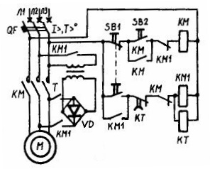
To start the idle speed of an induction motor with increased power with the switching of the stator winding from a star to a delta, you can use the diagram in Fig. 3. Switching in this circuit is done automatically as a function of time. By pressing the button SB2, the stator winding is connected to the network by the contactor KM. At the same time, the time relay KT and the coil KY are connected to the network, which connects the stator winding to a star using three contacts in the power circuit.
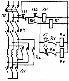
Rice. 3. Control circuit as a function of time of an induction motor by switching from Y to Δ
The motor starts and accelerates at reduced voltage. After a predetermined time interval, the KT relay turns off the KY contactor and turns on the coil of the KΔ contactor connecting the stator winding to the delta. Since there is an auxiliary contact KY in the circuit of the coil K∆, the closing of the contactor K∆ cannot occur before the closing of the contactor KMY.
Stepwise starting of multi-speed induction motors is more economical and is done as a function of time.Let's consider an example of a step-by-step start of a two-speed motor with a single winding (Fig. 4). The stator winding goes from delta to double star at double speed.
Rice. 4. Control circuit as a function of induction motor step start time
The motor is switched on by contactor KM to the first speed stage, and by contactors KM2 and KM1 to the second. To turn on the motor to the first speed, pressing the button SB2 turns on the coil of the contactor KM and its power contacts KM in the main circuit. The delta connected stator winding is connected to the network. The coil of the time relay KT is energized, and its closing contact (in the circuit of the coil KM) is closed.
 A step-by-step start of the engine at the second speed of rotation is carried out using an intermediate relay K, the circuit of which is closed by the start button SB3. The K closing contacts bypass the two start buttons and the K opening contact de-energizes the KT time relay. The closing contact KT in the circuit of the coil KM turns off with a return delay, due to which the coil KM in the first period of starting turns out to be closed and the motor turns on at the first speed.
The contact of the KM block in the circuit of the coil KM2 and KM1 opens. These coils are also disconnected from the open contact KT, which is delayed on return. After a certain period of time, the closing contact KT will turn off the coil KM, and its opening contact will turn on the coils of the contactors of the second speed of rotation KM1 and KM2. Their main contacts in the supply circuit will switch the stator winding to double star and connect it to the mains.
Therefore, the engine first accelerates to first gear and then automatically switches to second gear. Note that the preliminary connection of the stator winding to a double star and its subsequent inclusion in the network is carried out first by turning on two closing contacts of the power supply KM2, and then three closing main contacts KM1. Such a switching sequence is achieved by the fact that the coil KM1 is connected to voltage through the contact of the closing block KM2. The engine is stopped by pressing the «Stop» button, marked on the diagram with the letter SB1.
In fig. 5 shows a diagram of the automatic start of a parallel-excited DC motor as a function of time. By closing the QF circuit breaker, the motor is prepared for starting. The current flows through the circuit consisting of the winding of the time relay KT1, the armature of the motor M and two stages of the starting rheostat R1 + R2.
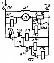
Rice. 5. Control circuit as a function of time of an excited DC motor
Due to the high resistance of the coil of the relay KT1, the current in this circuit is very small and has no effect on the motor, but the relay itself is triggered and its open contact in the circuit of the contactor KM1 opens. In the coil of the second time relay KT2, connected in parallel with the resistance R1, such a small current is branched that it cannot be turned on. The LM field winding of the motor also turns on.
The motor is started by pressing the SB2 button. At the same time, the contactor KM and its contact in the armature circuit of the motor are turned on. The large starting current is limited by two rheostat stages R1 and R2.Part of this current is branched into the coil of the KT2 relay and when actuated it opens its KT2 contact in the KM2 contactor circuit. Simultaneously with the closing of the armature circuit M, the working contact of the contactor KM short-circuits the coil of the relay KT1.
After a certain time interval when the relay returns, KT1 will close its KT1 contact in the KM1 contactor circuit. This contactor with its working contact KM1 will short-circuit the first stage R1 of the starting rheostat and the winding of the time relay KT2. With a return delay, its working contacts KT2 will turn on the contactor KM2, which with its working contacts KM2 will short-circuit the second stage R2 of the starting rheostat. This completes the engine start.
When the SB1 button is pressed, the KM contactor will trip and disconnect its main contact in the armature circuit. The armature remains energized, but it turns out that it is connected in series with the relay coil KT1, due to which a small current flows through it. Relay KT1 will work, open its contact in the circuit of contactors KM1 and KM2, they will turn off and open their contacts, short-circuit resistances R1 and R2. The motor will stop, but its field winding remains connected to the mains and thus the motor is prepared for the next start. Complete shutdown of the engine is done by turning off the automatic input switch BB.
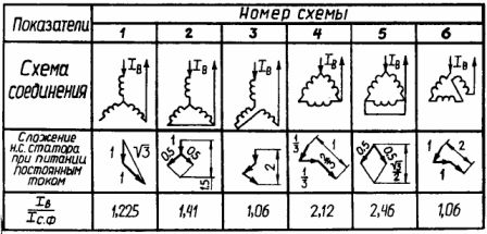
Dynamic braking of motors is also performed as a function of time. For dynamic braking, for example, an induction motor, the stator winding is disconnected from the alternating current network and, according to one of the schemes shown in table 1, is connected to a direct current source.In the forestry and woodworking industry, direct current is obtained from special semiconductor rectifiers. In this case, there is no need for a special source of direct current.
When the stator winding is turned on according to one of the schemes (see Table 1), a stationary magnetic field is created in the winding to the rectifier. In a stationary field, the rotor of the motor continues to rotate by inertia. In this case, an alternating EMF and current will be created in the rotor of the motor, which will excite an alternating magnetic field. The changing magnetic field of the rotor when interacting with the stationary field of the stator creates a braking torque. In this case, the stored kinetic energy from the rotor and the drive is converted into electrical energy in the rotor circuits, and the latter into heat.
Thermal energy is dissipated from the rotor circuit to the environment. The heat generated in the rotor will heat up the motor. The amount of heat released depends on the current in the stator winding when it is supplied with direct current. Depending on the scheme adopted for turning on the stator winding when it is supplied with direct current, the ratio of current to phase current of the stator will be different. The ratios of these currents for various switching schemes are shown in a table. 1
The dynamic braking circuit of an induction motor is shown in fig. 6.
Rice. 6. Scheme of dynamic braking of an induction motor
By pressing the start button SB1, the KM line contactor turns the motor on to the AC network, its closing block contact switches the KM coil to self-powered.The opening contact KM disconnects the supply circuit of the brake contactor KM1 and the time relay KT. When the SB button is pressed, the KM line contactor is de-energized and the KM1 contactor coil circuit will be energized.
Contactor KM1 includes its contacts KM1 in the circuit of transformer T and rectifier V, as a result of which the stator winding will be supplied with direct current. To prevent random independent switching of the line contactor, the opening contact of the block KM1 is connected in series with its coil KM. Simultaneously with the brake contactor, the time relay KT is turned on, which is configured so that its open contact KT will turn off the coil KM1 and the time relay after a certain time interval. The time relay setting KT is chosen so that the relay actuation time tkt is equal to the sum of the motor deceleration time tT and the correct contactor KM1 tripping time.