Automatic blocking and signaling circuits
 In multi-motor drives, a defined sequence of switching on, off, reversing, regulating and stopping different motors is usually provided by means of interlocking connections between the control circuits of individual electric motors.
Here are some auto-locking schemes used in controlling two squirrel-cage rotor motors.
According to the diagram in fig. 1, a, the start of one motor excludes the possibility of turning on the other, which is provided by the auxiliary contacts K1 and K2, which open when the contactor of the other motor is actuated. The same circuit can be used to remotely control each motor individually without blocking. To do this, the two-position switch SM must be set to the right position when both pairs of contacts 1 and 2 are closed, bypassing the auxiliary contacts K1 and K2.
According to the diagram in fig. 1, b, the first engine (not shown in the figure) is turned on by pressing the start button SB1. Along with it, the second engine turns on automatically. But the second engine cannot start when the first one is not working.Turning one of the engines on causes the other engine to stop immediately. In automatic operation, the SM switch is set to the left position, where contacts 1 and 3 are closed, and in separate control, the switch is set to the right position, when contacts 2 and 4 are closed.
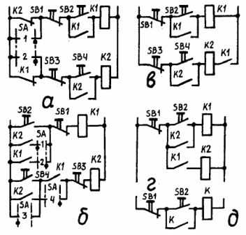
Fig. 1. Blocking schemes of two asynchronous motors: a — blocking exceptions; b and c — dependent blocking; driver — when two engines work together
According to the diagram in fig. 1, the motors are switched on one by one: first, the first motor with the SB1 button, then the second motor with the SB2 button. It is possible for the first engine to work separately, but the second engine can only work together with the first. The starting control scheme is greatly simplified if the motors are only to be operated together.
According to the diagram in fig. 1, d, this is provided by two contactors and a common start button, and in the scheme of fig. 1, d — from a common contactor. In all the above schemes, the motors are stopped using the corresponding SB buttons.
No matter how rationally the engine control scheme is composed, the possibility of malfunctions in the operation of its individual elements must be taken into account. Reliability in operation depends not only on the quality of the equipment and its installation, but also on the construction of the control circuit, therefore it is necessary to provide various types of alarms for the operating modes of the circuit and avoid emergency modes. In order to exclude the spontaneous continuation of work after restoration of voltage without reconnection of the circuit, the operator provides information signaling (Fig. 2). Despite the simplicity of the version of Fig.2, ah, it may give a false alarm when the lamp burns out.
A more reliable option is Fig. 2, b, since if one of the two lamps burns out, it will not give false information. If the circuit has free contacts, then the variant of fig. 2, with is more reliable. The voltage recovery signal in the presence of the KV voltage relay can be given as per the scheme of fig. 2, d. After the voltage is removed, the restart is carried out by the trigger button SB. An open circuit of relay or contactor coils should not be a cause of incorrect operation, therefore normally open contacts that close when the coil circuit is open should not be included in the control circuits.
In the circuit of fig. 2, e a spacecraft monitoring relay of the current in the windings of critical units is used, which is connected in parallel with the coil of the contactor K. The open signal in the coil K is indicated by the lamp HL. If the armature of the contactor K sticks when the voltage is removed, the signal that the contactor remains on is provided by the illumination of the lamp HL1.
One variant of the audible alarm circuit is shown in fig. 2, e. This scheme is used to monitor the correct operation of four engines. Once all four engines are started, the alarm in this circuit is automatically prepared for activation. In this case, the closing contact of the fourth motor K4 turns on the relay for preparing the sound signal KV, and the opening contacts in the section ab open. In this case, the self-locking and blocking contacts of the KV relay are closed.
In the event of an overload, for example, of one of the motors in section ab, one of the opening contacts will close and the HA alarm will immediately sound. To remove the buzzer, press the SB button connected in series with HA, thereby opening the circuit of the KV relay and its KV contacts. By pressing the SB1 button, the motors are automatically stopped and the KH auto stop relay is activated.
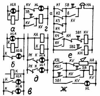
Rice. 2. Signaling schemes: a, b, c — examples of information signaling; d and d — with voltage and control relays; f, g — emergency
The open contact KH relay will switch off the supply circuit to the coils of contactors K1 K2, K3 and K4 (contactors not shown in the diagram) and with the other KN contact will switch off the KV relay which will switch off the HA buzzer. To check the beep, press the SB button.
In order to control the upper and lower levels of sawdust in the chipboard manufacturing hopper, an audible alarm can be used, shown in Fig. 2, g. When the chips reach the upper level of the hopper, the relay KSL will turn on, and its closing contact will turn on the beeper HA. When the chips in the hopper fall below the set level, the RSL1 low level relay contact will close and sound the buzzer.
By pressing the SB button, the beep is removed. The SB button will turn on the relay to remove the KV signal, and its open contact will turn off the HA signaling. The KV relay will remain energized through a self-latching contact until the control voltage is removed. By pressing the button SB1, the operation of the sound alarm is checked.
In fig.3 shows a diagram of electrical signaling of two process parameters.
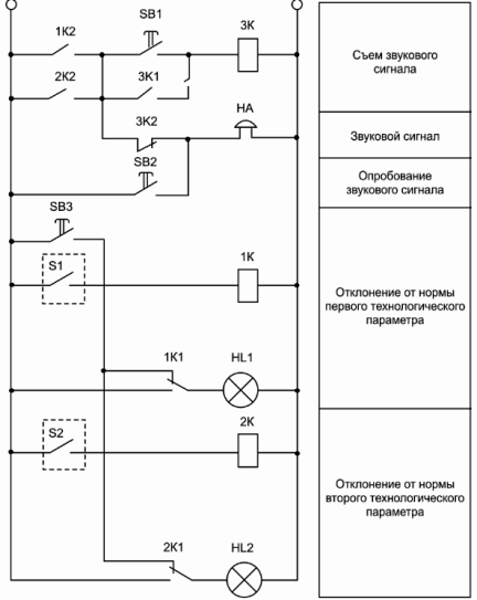
Rice. 3. Alarm circuit
In case of deviation from the norm of one of them, for example the first one, the process contact S1, located in the corresponding measuring device or signaling device, closes. This includes the relay 1K, which with its switching contact 1K1 turns on the signal lamp HL1 and turns it off from the alarm test button SB3.
At the same time, the closing contact 1K2 of relay 1K through the opening contact 3K2 of the disconnected relay 3K turns on the bell. The bell is activated by the audible alarm release button SB1, when pressed, the 3K relay through its 3X7 contact contact is self-latching, the bell is disconnected from the open contact.
If in this state of the circuit the second process contact S2 closes, then when the buzzer is removed, only the signal lamp HL2 lights up and the buzzer will not sound. The circuit will return to its original state after both process contacts S1 and S2 open, causing all relays to de-energize. Buttons SB2 and SB3 are intended for testing the bell and signal lamps.