Motor control circuits as a function of speed
 In motor control, the speed is monitored as a function of the motor rotor speed to influence the corresponding control elements as it changes.
Speed control relays or small measuring electric generators can be used in motor starting control circuits. However, they are used extremely rarely for these purposes due to the complexity of the design, high cost and insufficient reliability. Therefore, the engine speed is controlled by indirect methods. In asynchronous and synchronous motors, the rotational frequency is controlled by the emf and frequency of the rotor current, and in direct current motors by the armature emf.
In fig. 1, a and b show schemes for automatic starting of a parallel-excited DC motor depending on the frequency of rotation and depending on the EMF and the armature voltage from the time of starting. The control of the rotation frequency is carried out by measuring the EMF of the motor, which varies in proportion to the rotation frequency.
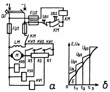
Rice. 1.Control circuits as a function of speed: a and b — circuit and starting diagram of a parallel-excited DC motor
Since the EMF is proportional to the engine speed, the automatic input of individual stages of the starting rheostat is carried out at a certain magnitude of the actuating voltage of the accelerating contactors KM1, KM2 and KMZ, each of which is set to a certain retraction value. By pressing the starter buttons SB2 turns on the KM line contactor. All resistances R1, R2, R3 will be connected in series with the armature winding and will limit the current.
At a certain speed n1, the voltage Uy1 of the coil of the contactor K1 is

where Here This is the coefficient of the machine.
When Uy1 will be equal to the pull-down voltage, the contactor KM1 will operate and short-circuit the resistance R1. A further increase in the speed of rotation until the rotation of n2 and n3 will lead to an increase in the voltage on the coils of the contactors K2 and a short circuit to values


In this case, the contactors K2 and the short circuit will work in series and short circuit the resistances R2 and R3. After short-circuiting the resistance R3, the starting process will be completed and the motor can run for a long time.
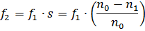
The EMF in the rotor circuit of the induction motor is proportional to the slip, i.e. E2s = E2s. Here E2 is the emf of a stationary rotor.
The lower the slip, the lower the EMF, that is, the higher the motor rotor speed. To control the starting of AC motors with a wound rotor, relays are used that control the value of EMF in the rotor circuit.The corresponding devices (relays, contactors) that short-circuit starting resistances are adjusted to these voltages.
For the control of wound-rotor induction motors and synchronous motors, the frequency method can also be used as a function of speed. This method is based on the known dependence of the frequency of the rotor current f2 on the frequency of rotation of the stator field n0 and the rotor n2, i.e.
Since each rotor speed corresponds to a certain f2 value, a relay set to that frequency and connected to the motor rotor circuit will act on the contactor coil circuit. The contactor will short circuit the resistance stages at a given speed.
Braking by opposing motors is done depending on the speed speed control relay SR. In Fig. 2, a, b show examples of stopping asynchronous motors by opposition.
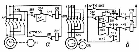
Rice. 2. Schemes of stopping asynchronous motors by means of opposition: a — non-reversible; b - reversible
Let's take a look at how these schemes work.
Pressing the SB2 button turns on the coil of the contactor KM (see Fig. 2, a), which closes the power contacts and blocks the SB2 button. At the same time, the contact of the opening block KM in the circuit of the coil of the brake contactor KM1 and the speed control relay SR disconnects them from the network. When the motor rotor reaches a certain speed, the SR contact will close, but this will no longer cause the KM1 contactor to operate. The engine continues to run normally.
Stopping the motor with a counter-switching brake is done by pressing the SB button.At the same time, the coil of the contactor KM is neutralized, and its main contacts disappear and disconnect the motor from the network. The KM opening contact in the brake contactor circuit of KM1 will close. Since at this moment the contact of the speed control relay SR is closed, the main contacts of the brake contactor are immediately turned on and the stator winding is switched to reverse, the magnetic field will begin to rotate in the opposite direction, i.e. the rotation of the rotor and the motor will be stopped by counter switching. The speed of the rotor decreases and at a certain small value its contacts of the RKS speed control relay will open and disconnect the motor from the mains.
In the case of reverse control with opposite braking (Fig. 2, b), the motor is started forward by pressing the button SB1, which, by closing the circuit of the coil of the contactor KM1, ensures that the motor is connected to the network. The motor rotor will start rotating and when it reaches a certain speed, the closing contact SR1 of the speed control relay will close and the opening contact SR2 will open.
Switching on the coil of the contactor KM2 will not happen because the opening contact of the contactor KM1 has broken its circuit. In this position, the motor will continue to run until the SB button is pressed. When the SB button is pressed, the circuit of the coil KM1 is turned off. This will close the break contact KM1 and the coil circuit of the contactor KM2 will receive power.
The motor stator winding will engage to reverse. As the rotor continues to rotate in the same direction by inertia, opposition braking occurs.When the speed decreases to a certain small value, the speed control relay opens its contact SR1, the contactor KM2 will turn off and disconnect the motor from the network.
To start the engine in reverse, press the SB2 button. The whole process will be similar to the one described. Now the role of the brake contactor is played by the KM1 contactor, and the SR2 contacts of the speed control relay will control the braking process.
Automatic starting of a synchronous motor is associated with well-known difficulties, since in this case it is necessary not only to limit the starting current, but also to synchronize the machine with the network.
The control circuit for a low power synchronous motor is shown in Fig. 3. Inrush current limitation is provided by active resistances included in the stator winding. Before starting the engine, turn on the automatic input switches QF and QF1 of the AC and DC mains, which provide maximum and thermal protection. By pressing the start button SB2, the coil of the contactor KM is turned on, and the stator winding of the synchronous motor through the main contacts of KM is connected to the network through the starting resistors Rn. The coil is self-locking and its contact in the DC circuit includes the locking relay KV, the closing contact of which, closing, prepares the coils of contactors K1 and K2 for switching on.
The frequency relays KF1 and KF2 in the excitation circuit of the LM rotor operate depending on the engine speed. At start-up, when the rotor slip is greatest, the breaking contacts of the relays KF1 and KF2 open.The opening of the coils occurs before the KV blocking relay turns on and the K1 coil will not receive power. Relay contacts KF1 and KF2 will close again when the engine RPM reaches approximately 60-95% synchronously in accordance with relay regulation.
After closing the contacts of the relay KF1, the coil of the contactor K1 will turn on, its contacts in the main circuit will short-circuit the starting resistors Rp and the stator will turn on to full line voltage. When the open contacts of the relay KF2 are closed, a circuit is created to supply the coil of the contactor K2, independently of the contactor K1, its contact opens at a speed of approximately 60% of the synchronous speed.
Contactor K2 has two windings: one main, pulling KM1 and the second winding KM2, designed to release the lock, which is provided with the contactor. After switching on the take-up coil KM1, the closing contacts K2 close in the excitation circuit, and the opening contacts K2 open, disconnecting the rotor winding from the discharge resistors R1 and R2 and connecting the rotor to the DC network.
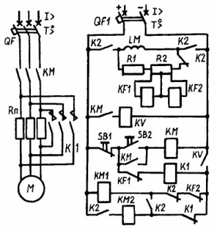
Rice. 3. Synchronous motor control scheme
The contacts of the contactor K2 work in the following order. N / O contact K2 opens in the supply circuit of the pickup coil, but the blocking action keeps the contactor energized. The closing contacts K2 close in the supply circuit of the two coils and in the circuit of the coil KM2, preparing the circuit for subsequent switching on. Coil K2 will be de-energized as soon as the locking mechanism is released from coil KM2. The motor is disconnected from the mains by pressing the SB1 button.Coil K1 releases its opening contact in the circuit of coil KM2, which releases the latch and turns off coil KM1, after which the circuit returns to its original position.