Motor control as a function of current
 Motor control can be done depending on the strength of the stator current. The starting circuit as a function of current of a wound-rotor induction motor is shown in Fig. 1 a.
At the moment of starting, the current reaches the value I1, and after a certain time interval it decreases to the value I2 (fig.b). At this point, part of the starting resistance in the rotor circuit is automatically short-circuited, the current rises to the value I1, then drops again to the value I2, which causes another part of the starting resistance to short. This process is repeated until all stages of the starting resistance are short-circuited. For these purposes, an overcurrent relay is used, the windings of which are included in the power circuit of the motor.
When you click on start button SB1 (see fig. A) the contactor KM is activated, the main contacts of which connect the motor to the network at the common starting resistance in the rotor circuit. In this case, the coil of the KA relay receives power, the opening contacts of which are in the circuit of the accelerator coil K1.The KA relay is set so that the response time is shorter than that of the K1 contactor. In addition, its breaking contacts at the maximum permissible value starting current open, and when the current decreases to its switching value, they close again, due to which the coil K1 is turned on through the contacts of the relay KA at the moment of short circuit of the starting resistance stage.
Relay KA will operate before acceleration contactor K1 is energized, and the motor will accelerate when the starting resistance is fully introduced. As the starting switching current decreases, the contacts of the KA relay will close and the coil K1 will turn on. At the same time, contact K1 closes, providing self-powering of the coil independently of the relay KA, and the contact in the control circuit opens, preventing premature inclusion of the accelerator K2.
Since the supply contacts K1 are part of the short circuit of the starting resistance, the stator current increases to the maximum value and the relay KA, when triggered, opens its contacts in the supply circuit of the coil K2. When the motor reaches sufficient speed and the stator current drops back to the switching current, the contacts of relay KA will close and turn on coil K2, which short-circuits the second stage of starting resistance to its contacts.
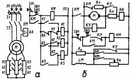
Rice. 1. Control circuits depending on the current: a — asynchronous motor with a phase rotor; b — DC motor with parallel excitation
In this case, the stator current increases again, the KA relay will operate and open its contacts. Coil K2 will not lose power as it will have time to close with auxiliary contacts K2.A further decrease in the stator current after the next acceleration will cause the winding K3 to turn on and short-circuit the last stage of the starting resistance. Pressing the SB button stops the motor and the circuit is ready for the next start. Using the current relays configured to return at a current of 12, various electric drives can be stopped and reversed. The disadvantage of control circuits in the current function is the rather large number of contacts.
For irreversible control of a parallel-excited DC motor of several kilowatts, a single stage of the starting rheostat can be used (see Fig. C). The diagram shows: regulating resistance RB in the excitation circuit; discharge resistance Rp connected in parallel with the excitation coil LM; a braking resistance RT connected in parallel to the armature M when disconnected from the network and a starting resistance RP connected in series to the armature circuit during the starting period. To produce maximum flux at start-up, the LM field coil in the initial position is turned on at full voltage.
When the SB2 button is pressed, the armature of the motor from the line contactor KM is connected in series to the network with the resistance RP. The starter control relay SC operates as a function of the armature current. As the current increases, the closing contact of KA manipulates the resistance RB, increasing the excitation magnetic flux, and as the current decreases, the contact of KA opens and the LM coil is connected in series with the resistance of the rheostat RB, due to which the magnetic current decreases.
When the motor is started, the increased starting armature current turns on the KA relay and the LM coil creates maximum flux. When a certain speed is reached, the acceleration contactor K is turned on, the starting resistance RP is short-circuited, after which the motor operates according to its natural characteristics. When the armature current decreases (as a result of motor acceleration) before the KA relay energizes, the KA contact in the excitation circuit will open.
The LM winding will turn on in series with the RB resistance, causing the field flux to weaken and the armature current to increase accordingly. The KA relay will operate again, increasing the flux and simultaneously increasing the motor speed. During startup, the spacecraft relay is triggered several times until the motor reaches the speed set by the RB control rheostat. Such a vibrating device operating as a current function simplifies the circuit compared to control circuits as a function of time.
When the motor is turned on by pressing the SB1 button, the armature is turned on from the opening contact KM to the braking resistor RT and dynamic braking is performed automatically. At the beginning of the stop, the magnetic field is slightly weakened due to the opening of the KM contact on the slider of the regulating rheostat, and the excitation current passes through the entire resistance RB. As the motor speed decreases further, the acceleration contactor K is de-energized and the flux increases as the excitation coil is switched on to full line voltage through the opening contact K, resulting in an increase in the braking torque.