Contactor control and motor protection circuits
 Depending on the function to be performed, there are different contactor motor control circuits.
Figure 1a shows a combined scheme of an irreversible magnetic starter... In it, the arrangement of elements coincides with the arrangement in nature, that is, all the elements located in the starter box are grouped on the left side of the diagram, and push button station with «Start» and «Stop» buttons shown on the right side of the diagram.
The button station is usually located some distance from the magnetic starter… To understand the principle of operation of the motor control circuit, detailed (basic) diagrams are usually used (Fig. 1.b). By pressing the SB2 start button, the KM contactor coil circuit is closed, which includes three KM contacts of the motor supply circuit. In this case, the block contact KM connected in parallel with the start button SB2 also closes. This allows you to energize the KM coil when the SB2 button is released.
The motor is stopped by pressing the SB1 button while the coil turns off and releases the power (main) contacts and the auxiliary contact. When the SB1 button is released, the circuit of the coil KM will be de-energized. To restart the engine, press the SB2 button again.
This circuit also provides the so-called zero protection, that is, if the mains voltage disappears or drops to 50-60% of the nominal, the KM coil will not hold the KM power contacts and the motor will be turned off. When a voltage appears or increases to a value close to the nominal value, the magnetic starter will not engage spontaneously. To turn it on, you need to press the start button again.
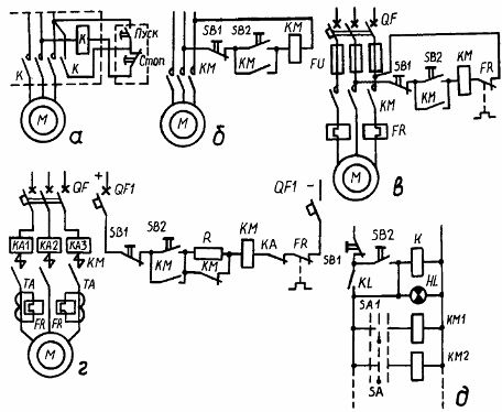
Rice. 1. Motor control and protection schemes: a — combined and b — detailed scheme of an irreversible magnetic starter; c — engine protection by means of fuses and thermal relays; d — diagram of the powerful engine control station; d — zero protection from an intermediate relay
Protection of the motor from overheating of the winding is carried out during prolonged overloads thermal relays FR, and protection against large overloads or short circuits is provided by fuses FU or circuit breakers QF (Fig. 1, c). To protect against prolonged overloads, two thermal relays are used, since with one relay, in the event of a blown fuse, in series with which the heating element of this relay is connected, the motor will be connected to a single-phase network and they will not be protected . The breaking contacts of these relays are connected in series with the starter coil. When one of them opens, the KM coil is de-energized and the motor stops, as when the SB1 button is pressed.
A high power motor control station is shown in fig. 1, d. Short-circuit protection is provided by the overload relay KA1 — KA3, overload protection is provided by thermal relays FR connected through current transformers. The coil of a three-pole contactor is supplied with direct current. To reduce the current in the contactor coil after its inclusion in the circuit, an additional resistance R is introduced, which was previously shorted by the open contact KM.
In manual control circuits with multiple controllers, switches, or other devices, intermediate relays are used to provide neutral protection. (Fig. 1, e). To apply voltage to the control circuit, press the button SB2, thereby turning on the intermediate relay K, which includes its closing contact K and the signal lamp HL, indicating the presence of voltage in the control circuit. After releasing the SB2 button, the relay coil will be blocked while the circuits of the SM1 controller, SM packet switch, etc. and the coils of contactors KM1, KM2, etc., will be energized.
In the considered schemes, the self-locking contacts are necessary for the continuous operation of the motors. Often in practice the engine only needs to run when the start button is pressed, for example in lifting machines. In this case, there is no Stop button in the control circuit (Fig. 2, a). Sometimes it is necessary to ensure the operation of the drive in two modes, that is, to turn it on for a short time when setting up the machine or for a long period of time. Then, with a short press of the button SB2 (Fig. 2.b), the coil of the contactor KM will turn on and the self-locking contact of the KM will close, while the motor will run when the button SB2 is released.
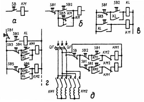
Rice. 2. Types of control circuits for asynchronous motors: a — in jogging mode; b and c — during prolonged work and jogging; d — simultaneous inclusion of several engines; d — stepless start of a two-speed motor
For motor control mode, press the SB3 button, its closing contact turns on the coil of the contactor KM, and the opening contact breaks the self-locking circuit of the contactor. The disadvantage of this circuit is that the open contact of the SB3 button can close before the contact of the KM block opens and the motor does not turn off. The circuit shown in fig. 2, f, is devoid of this defect.
For continuous operation, pressing the SB2 button turns on the intermediate relay K. One of the contacts K turns on the coil of the contactor KM, and the other simultaneously blocks the SB2 button, thereby turning off the operation of the engine with the start button released. To start operation, press the SB3 button and hold it for the required time.
Figure 2d shows a scheme for starting several motors at the same time from one start button using an intermediate relay ... Button SB2 turns on relay K, the closing contacts of which simultaneously turn on the coils of contactors KM1, KM2, etc. Stop all motors simultaneously with the SB1 button. To turn each motor on and off individually, use buttons SB3, SB4 and SB5, SB6, etc. respectively.
A stepless starting diagram of a two-speed two-winding squirrel-cage rotor motor shown in Fig. 2, e. To start the engine at the first speed, the button SB1 is used, at the second - SB2.Both buttons are mechanically interlocked to prevent the engine from engaging in two speeds at the same time.
The starter circuits are also blocked electrically. So, when, for example, coil KM1 is actuated, the opening contact breaks the circuit of coil KM2, excluding the possibility of its inclusion. To switch to the second speed, you need to press the button SB2, while the circuit of the coil KM1 is broken and it turns off. The coil of the KM2 circuit receives power and turns on the motor at the second speed.
Reverse control of asynchronous motors is carried out using two contactors (Fig. 3, a).
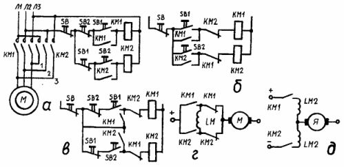
Fig. 3. Engine control schemes: a — reversible magnetic starter with mechanical blocking; b — the same with electrical blocking; c — a combination of options a and b; d and e — starting and reversing low power DC motors
Contactor KM1 is used to engage the motor in forward and KM2 is used in reverse. To prevent accidental simultaneous switching on of the two contactors, which leads to a short circuit, the circuit uses (see Fig. 3, a) mutual mechanical blocking with two interrupting contacts of the buttons SB1 and SB2. Pressing the button SB1, turn on the circuit of the coil KM1 and disconnect the coil circuit KM2.
When the SB1 and SB2 buttons are pressed simultaneously, the circuits of the coils KM1 and KM2 are broken and none of the contactors will turn on. Blocking is carried out by two interrupting contacts KM2 and KM1, included in the circuits of the coils KM1 and KM2, respectively (Fig. 3, b). To reverse the engine in this scheme, you must first press the SB button.
The circuit in fig. 3, c is a combination of the two previous circuits, that is, there is double blocking.The SBI button turns on the contactor KM1, and the circuit of the coil of the contactor KM2 is broken by the simultaneously open contact of the button SB1 and the contact of the block KM1.
Figure 3, d and e shows the simplest schemes for starting and reversing low-power sequentially excited motors ... Such motors are connected to the network without starting rheostats. According to the diagram in fig. 3, d, the starting and reversing of the motor with series excitation is carried out by means of two intermediate relays. The motor is reversed by reversing the direction of the current in the LM field coil. In motors with two series field windings creating magnetic fluxes in opposite directions, the switching and reversing circuit has only two contact contacts (see Fig. 3, e).
As can be seen from the considered control schemes, it is easiest to automate the process of starting and reversing squirrel-cage rotor asynchronous motors. In this case, all control when starting is reduced to connecting the motor to the power network, and when stopping - to disconnecting from the network.
More complex is the automation of starting, stopping and stopping of induction motors with a phase winding of the rotor, induction squirrel-cage motors of increased power, DC motors of medium and high power, multi-speed induction motors with step start, as well as synchronous motors. These engines are controlled as a function of time, speed and current.
In addition to the above cases, engine control can be performed and according to the path principle, when the engine starts and slows down when the working body reaches a certain position in space.Systems performing such functions are called open-loop systems because they have no feedback between the output value and the input value.