Schemes for the automation of continuous transport mechanisms
 The purpose of automation of continuous transport mechanisms is to increase their productivity and reliability. The requirements for the level of automation of these mechanisms are determined primarily by the nature of the functions they perform.
Escalators, multi-cabin passenger elevators and circular passenger ropeways perform independent functions, therefore the automation of these mechanisms is mainly reduced to the automated start and stop of the electric drive with the limitation of acceleration and sudden movement and providing the necessary protections and interlocks that guarantee passenger safety. It should be noted that for installations that transport people, the presence of a person who controls the operation of the installation is necessary. Therefore, some of the control functions can be assigned to the operator, which simplifies the circuit and increases the reliability of its operation.
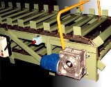
For conveyors that perform part of the functions in the general technological process of production, automation is subordinated to the tasks of the complex automation of this production. Conveyor installations included in technological complexes can be complex flow-transport systems of great length. Their management and control of the health of the mechanical and electrical equipment is concentrated in the control room, where the dispatcher monitors the operation of the conveyors with the help of light boards, mnemonic schemes and audible alarms. For operational purposes, for the repair, overhaul and adjustment of individual conveyor lines, in addition to the centralized one, local control is also provided from the console located directly within the boundaries of the drive station.
Elements of the conveyor control circuit located on the local control panel are shown in fig. 1. With centralized control from the control room, switching on and off the starting contactor of the gearbox is carried out using the relays RUV and OBO, respectively. When the PR switch is moved to the MU (local control) position, the drive station can be switched on and off separately using the «On» buttons. And «Shutdown». The PU switch allows by disconnecting the device from the remote control to connect to the dispatch office via the TF phone.
In the general case, depending on the nature of the technological process, the automation system of a complex of conveyor lines of an industrial enterprise must perform by turning on and off various conveyors in a certain sequence in strict accordance with the production process; ensuring the necessary speed of transportation of goods and, if necessary, coordinating the speed values of different conveyors, as well as technological and emergency blocking of equipment.
Malfunctions in the equipment can lead to disruption of the entire technological process (conveyors) or danger to human life (rope lines, escalators). Therefore, a large number of safety interlocks are used in the automation schemes of these installations. The most typical of them, due to the peculiarities of the operation of these mechanisms, perform the following functions:
1. Monitoring the good condition of the traction element (belt, rope, chain) and stopping the installation in case of excessive stretching of the traction element, weak tension, coming off the guide rollers, deflection drums and rollers;
2. stopping the installation when the speed increases excessively;
3. stopping the installation in case of prolonged start-up,
4. prevention of clogging of hoppers of cargo-overloading devices;
5. ensuring the necessary sequence of starting and stopping the mechanisms of the technological complex.
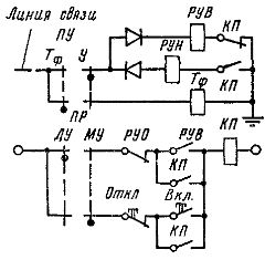
Rice. 1. Control circuit elements for starting and stopping the conveyor on the local control panel.
Rice. 2. Schematic of the control unit for starting the conveyor.
The first two protections are provided by limit switches and a speed relay.It should be borne in mind that due to the possible slippage of the rope or belt of the drive pulley or drum, the engine speed does not yet characterize the speed of the traction element, therefore the speed sensors must record the movement of the traction element. To do this, they are mounted either on a support roller for conveyors (usually on its reverse idle branch) or on a take-off roller for ropeways.
As a speed sensor, non-contact induction sensors are widely used, in which a rotating rotor - a permanent magnet creates an EMF proportional to the speed in a stationary stator winding. If the pulling element breaks, the speed relay gives a signal to turn off the electric drive. In mechanisms for transporting people (for example, cable cars), safety devices are additionally included that prevent the car from accelerating downwards. Overspeed protection works in a similar way and is implemented with a centrifugal type relay.
Due to the large inertial masses and static loads, the launch of the conveyors takes a long time and is accompanied by a significant heating of the engines. Conveyor overload, low voltage, some types of malfunctions in mechanical and electrical equipment can lead to an additional delay in the start-up process and, as a result, to an unacceptable increase in engine temperature.
In addition, overloading belt or rope conveyors can cause the traction element to slip on the drive element.At the same time, the completed process of starting the engine does not bring the conveyor to operating speed, and prolonged slippage leads to damage to the traction element, therefore, in all cases of continuous starting of the conveyor during the planned time, the device must be turned off. This is done automatically using the launch control unit (Fig. 2).
The gearbox start contactor includes the motor power circuit as well as the RCP start control relay, whose response time slightly exceeds the normal start time. At the end of the start-up process, the RCP circuit is broken by a contactor contactor of the last stage of acceleration Yn, provided that the motor current has fallen to the calculated value and the overload relay RP is turned off; the traction element has acquired operating speed and the open contact of the computer speed relay has opened.
When the supply circuit of the RKP relay is turned off, it stops timing and its contact in the KP circuit remains closed. In continuous start, the RCP power circuit remains on through the RP contact when the motor is overloaded or through the PC contact when the drive element slips. After the RCP delay time expires, it operates, closes the contactor and the start is terminated.
To avoid blockages of reloading devices in a multi-section belt conveyor, a certain sequence of turning on and off its motors is necessary. At startup, the conveyor sections are switched on sequentially, starting from the tail of the discharge, in the order opposite to the direction of the load flow.When stopping, the conveyor sections are shut down in the order of sections in the direction of load flow, starting from the head loading section.
Alternating switching on of the motors allows to simultaneously reduce the starting currents in the supply network. It is recommended to carry out an alternative start of conveyor lines depending on the speed of the traction element. This ensures that each subsequent section turns on after the previous one reaches the operating speed level. Stopping of conveyors, provided that all sections are fully unloaded and blocking of reloading containers, is carried out according to the principle of time. In this case, the loading of the head section is stopped first and the time delays for the alternate shutdown of the sections correspond to the duration required for the complete unloading of each section. If during operation one of the lines is interrupted, then all the lines preceding in the direction of the load flow must be disconnected one by one.
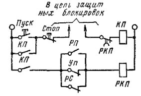
A schematic control diagram providing the indicated operations for three conveyor lines is shown in Fig. 3. The start of the conveyor is carried out from the central control panel through the universal switch UP, provided that the protective circuit of the RGP start ready relay is closed. In this case, as follows from the diagram, the starting contactor of the motor of the tail section KP3 is turned on first. The motor of the second section will start after the speed of the third section reaches the operating value and the speed relay PC3 is activated.
Rice. 3. Control scheme of the alternative start of a multi-section belt conveyor.
The load section motor will start after the end of the start of the second section when the speed relay PC2 is activated and KP1 is energized. Finally, the RZB loading hopper relay turns on, giving the command to load the conveyor.
Shutting down the engines with the help of the UE happens in the reverse order, but now as a function of time. First, the RZB is shut down by commanding the loading hopper to close. Then, after time delays, relays PB0, PB1 and PB2 turn off KP1, KP2, KPZ and the respective motors.
The scheme provides protection against blocking of the reloading containers, which turns off the transport sections that precede the overflowing hopper, as well as the loading hopper, by means of contacts RB1 and RB2.
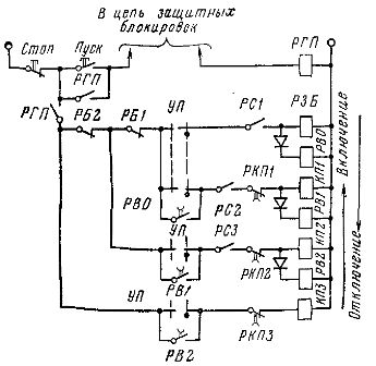
For this protection, a material level sensor is used on the electrode in the hopper (Fig. 4). When the electrode is shorted to ground by the transported material, the RB relay connected to the output of the EC sensor amplifier is energized. The high sensitivity of the sensor (up to 30 mOhm) allows it to be used for almost any transported material.
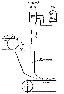
Rice. 4. Electrode sensor for the load level of the hopper.