Schemes for pulse switching on and off of relays using capacitors
 Schemes for pulsed switching on and off of relays due to currents charging or discharging capacitors spread of automatic lines in mechanical engineering.
In the diagram shown in fig. 1, a, relay K is activated when the contact of the command relay KQ closes due to the charging current of the capacitor C and returns to its initial state after the end of charging. The duration of the on state of the relay is determined by the capacitance of the capacitor and the supply voltage.
Resistor R serves to discharge capacitor C after opening contact KQ. Resistor R is chosen so that the current through it is less than the holding current of relay K. However, an increase in resistance leads to an increase in the discharge time of the capacitor, that is, the duration of the pause between two pulse switching of relay K. 1b, in which an open contact of the KQ relay is introduced into the resistor circuit with a small resistance R.
To reduce the pause, you can also use the diagram in fig.1, c, in which the discharge of the capacitor C takes place along the circuit R2 — R1 — VD. However, in this circuit, with a small resistance of the resistor R2, considerable power is dissipated.
The scheme in fig. 1, d with auxiliary relay K2. When contact KQ is closed, the main relay K1 is activated, and then relay K2, which turns off the resistor R in the coil circuit K1. The latter is held for some time due to the charging current of the capacitor C. Relay K2 returns when the contact KQ opens.
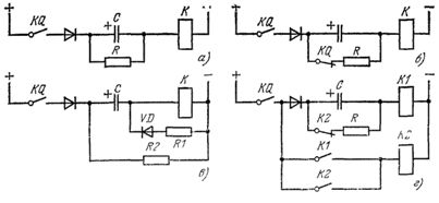
Rice. 1. Circuits for pulse switching of the relay from the capacitor charge currents
The described circuits are sensitive to sudden fluctuations in the supply voltage, which can lead to false relay operations. In networks with unstable voltage, schemes for pulse switching on the relay from the discharge current of the capacitor are recommended (Fig. 2, a-d).
In the diagram of fig. 2 and when the supply voltage is supplied, the capacitor C is charged. When the command relay KQ is actuated, the capacitor is discharged to the coil of the relay K, which is switched on in pulses. Resistor R limits the charging current of the capacitor.
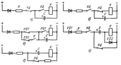
Rice. 2. Schemes of pulse switching on and off of the relay from the discharge currents of the capacitor
In the diagram of fig. 2, b, capacitor C is charged when relay KQ is actuated and discharged to the coil of output relay K after KQ is turned off.
In the diagram of fig. 2, after switching on the first command relay KQ1, relay K is activated and self-locking. When the second command relay KQ2 is energized, relay K returns with a time delay determined by the discharge time of capacitor C.
For pulsing the output relay K when the command relay KQ is turned off, the circuit in fig. 2, d.When KQ is triggered, capacitor C is charged along the circuit VD1 — R — KQ — C — VD2. When relay KQ returns, the capacitor discharges in the coil of relay K, which pulses.
In the diagram of fig. 2, e, relay K is pulsed when relay KQ is triggered and returned due to the charging and discharging currents of capacitor C, respectively.