Schemes for controlling the stepping motion of mechanisms
 For automation of mechanisms of this class, it is preferable to use rotary cams or non-contact command devices. The commander's shaft is connected to the drive shaft through a gearbox, the gear ratio of which is selected by the condition of rotation of the commander's drum in 1 step of the mechanism at an angle of 360 or 180 °. It is also possible to use position sensors (end or limit switches, proximity sensors) that are influenced by control elements connected to the mechanism. Several such elements are needed, and the distance between them is determined by the length of the step of the mechanism.
Relay stepper control schemes
In fig. 1, a and b show options for control schemes using command controllers. In the scheme of fig. 1, and two contacts of the SQ controller and a blocking relay K are used, which prepares the next contactor KM to turn on and then turn off in the middle of the movement of the mechanism. The contact closure diagram of the SQ controller is shown in Fig. 1, g. KV relay provides zero protection.
In the diagram of fig.1, b one circuit of the SQ controller and the time relay KT is used, the contact of which maneuvers the circuit SQ1 at the moment of the start of the next step of the mechanism. Figure 1, c -e shows options for 1-step pulse command schemes (automatic - relay KQ or manual push buttons SB1).
To automate the step movement in metal-cutting machines and automatic lines, a circuit node with two relays K1 K2 and two diodes VD1, VD2 is used (Fig. 1, e). At the end of each travel cycle, the travel sensor SQ is triggered and its open contact opens. After giving a step command (relay KQ), relay K1 turns on, the mechanism starts to move. When the sensor is released, the contact SQ closes, the relay K2 turns on and blocks itself, its contact in the circuit of the coil D7 opens.
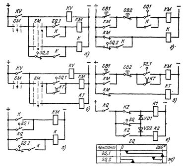
Rice. 1. Relay circuits for controlling the stepping movement of the mechanism
Relay K1 is now energized through the break contact SQ and diode VD1. After the end of the 1-step movement, the travel sensor SQ is triggered and the relay K1 is de-energized, stopping the mechanism. The next step is done after de-energizing and re-energizing the KQ relay.
Logic circuits
For easier comparison of the circuits in variants with logic elements, the same sensors as in the relay-contact circuits are shown. When sensors with non-contact output are used, the same functional units can be used with simplified input signal circuits. The stepper scheme, built on elements of the «Logic T» series, controlled by a command controller, is shown in fig. 2, a.
Elements D1-D3 provide matching of input signals with logic elements.The memory of the OR-NO elements D5.1 and D5.2 serves to store the initial position before starting when the handle of the SM controller is set to the zero position.
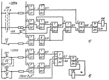
Rice. 2. Non-contact control schemes for stepping, movement of the mechanism: a — with control from the command controller, b — with automatic command
In this case, the controller circuit of the limit switch SQ is closed and 0 signals are received at input 6 of the memory element D5.2 and input 5 of the OR-NOT element D6.1. Signal 1 from the output of the element D2 is fixed by the memory D5.
Signal 1 from the memory output goes to input 3 of element D6.1. Therefore, 0 arrives at input 4 of element D4.2, which performs the AND function with zero signals. Input 2 of this element receives 1 from the output of element D4.1, therefore, at the output of element D4.2 there is a signal 0 and the output contactor KM is not included. After switching the SM controller to the "forward" position B, signal 1 arrives at the input of the OR-NOT element D4.1, and signal 0 arrives at input 2 of the element D4.2. 0 is stored at input 4 of this element as memory D5 remains on. In this case, signal 1 appears at the output of element D4.2, and the contactor KM is turned on through the amplifier D7. The engine starts and the mechanism starts to move.
In the middle of the step of the mechanism, the contact of the SQ controller opens and a signal 1 appears at the output of the element D6.2, which turns off the memory D5. Since signal 1 is already applied to input 5 of D6.1, the output of amplifier D7 remains unchanged.
After the appearance of signal 1 from the command SQ at the end of the step, signal 0 arrives at the input of element D6.1 from the output of element D6.2. .1 signal 1 appears respectively at the output of the element D4.2 — signal 0, the contactor KM disappears and the mechanism stops.
To reactivate the mechanism, it is necessary to place the handle of the SM controller in the zero position to activate the memory D5 and then move it to the "forward" position.
The SB button is used to set the memory to its initial state after powering up the circuit.
The stepper control scheme with automatic command is shown in Fig. 2, b. Elements D1 and D5 are used to match input signals with logic elements. The circuit is based on the use of a T flip-flop (D3 element of type T-102) with separate pulse inputs. Such a flip-flop is toggled when the input signal changes from 1 to 0. The flip-flop is preset to its initial state by applying a 0 signal to the R input.
In the initial state at the outputs of elements D1 and D5 there is a signal 0, and therefore at the outputs of elements D2.1 and D2.2 a signal 1. When the contact of the command relay KQ is closed or SB1 » start «is pressed, at the output of element D2 .1 0 signal appears, the flip-flop goes to state 1 and the contactor KM is turned on through the amplifier D4. The mechanism starts to move.
When the contact of the controller SQ is closed, the signal 0 appears at the output of the element D2.2, the trigger goes to state 0, the contactor is turned off and the mechanism stops. Button SB2 is used for manual emergency stop.