Monitoring the health of automatic control circuits
 To test and accelerate troubleshooting of complex automatic control schemes, special units of control schemes have been developed and implemented.
Insulation control in DC and AC control circuits
Insulation control in DC circuits can be done in different ways. One of the variants of the circuit is shown in fig. 1. Two high resistance DC currents PV1 and PV2 (with internal resistance 50-100 kOhm) are used. The middle point is grounded through a polarized relay KR of the RP-5 type (0.4-1.6 mA).
If the insulation is good, both voltmeters show half the line voltage. As the insulation deteriorates, the reading on one of the voltmeters decreases while the other increases. A current appears in the KR relay circuit. When the insulation of one of the poles is completely broken, the voltmeter connected to this pole shows zero, and the second voltmeter shows the full voltage of the network. The KR relay is activated and signals an insulation failure.
Buttons SB1 and SB2 are used to sequentially measure the insulation condition of each pole: when you press, for example, button SB2, a circuit is created: clamp (+) of the network — voltmeter PV1 — insulation of the negative pole — clamp (-) of the network. The SB3 button is used to check the status of the KR relay. Resistor resistance R = 75 kOhm (0.25 W).
The second version of the insulation monitoring circuit in DC circuits is shown in Fig. 2. Resistors R1 and R2 are 40 kΩ. Signaling relays KN1 and KN2 are PE-6 type (220 V). An MPA milliammeter with a scale of 30–0–30 mA is used to measure the insulation. The SM switch allows you to assess the insulation condition of each pole, which is especially important when the deterioration of the insulation of both poles is the same at the same time when the relay is not working.
Different methods are used to monitor insulation in AC circuits:
— fixing the asymmetry of phase or line voltage,
— measurement of the zero-sequence current occurring when a leakage current occurs in the network by conducting phase isolation to earth (in networks with solid earthing of the transformer neutral), etc.
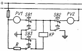
Rice. 1. Control of insulation in DC circuits (circuit with two voltmeters)
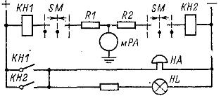
Rice. 2. Insulation control in DC circuits (circuit with milliammeter and two relays)
Troubleshooting charts
Various variants of schemes for accelerated testing of complex relay-contact circuits are shown in fig. 3. The feasibility of using a particular scheme must be determined taking into account the complexity of the control chain being operated.
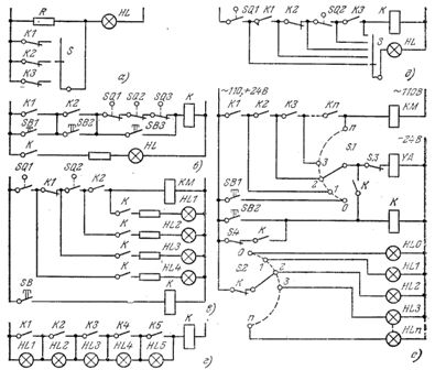
Rice. 3. Troubleshooting Charts
Scheme fig.3, a contains a fault finder — switch S and one signal lamp HL. The resistance of the resistor R is selected so that when the contacts of the tested automation relay K1-SC are open during normal operation, the HL lamp burns at full heat.
In the event of a fault in the circuit, the contacts of the fault detector S connected to the corresponding contacts of the devices under test are closed in sequence. If the coil of one of the relays is damaged, its contact closes, the resistor R is bypassed and the lamp HL lights up brightly.
In the diagram of fig. 3, b for troubleshooting applied control control buttons... The contacts of the tested devices (automation relay KL K2, motion switches SQ1-SQ3, etc.) are connected in series in the circuit of relay K. The lamp HL fixes the operability of this circuit. If the lamp does not light up, then by successively pressing the control buttons SB1-SB3 they detect the location of the fault in the circuit.
In fig. 3, c shows a scheme for detecting the location of the malfunction with the inclusion of warning lamps at all points of the controlled circuit of the executive device, for example, the contactor KM. To prevent the lamps from flashing during the operation of the mechanisms, a control relay K is introduced into the circuit. When a malfunction occurs, the operator presses the SB button. Relay K is activated and connected to the controlled points of the lamps HL1-HL4. If, for example, lamps HL1 and HL2 are off, and HL3 and HL4 are on, this indicates that the contact of the limit switch SQ2 is open.
In the diagram of fig. 3d, each controlled contact (K1-K5) is manipulated by a signal lamp (HL1-HL5).If the control relay K at a certain point in time turns out to be not turned on, the place of the malfunction is indicated by a glowing lamp, which is not overcome by the contact of the faulty relay. The parameters of relay K and lamps HL1-HL5 in this circuit are selected in such a way that relay K does not turn on through the lamp.
A troubleshooting diagram with one HL lamp and a fault detector S connected directly to the monitored circuit is shown in Fig. 3, e. If the executive relay does not turn on, switching the seeker S, they find the place of the circuit break and the contact of the damaged device.
In circuits with a large number of serially connected contacts, in order to speed up troubleshooting, step finders are sometimes used (Fig. 3, e).
When the «start» button SB1 is pressed, the coil of the solenoid YA of the stepper S is switched on through the first field S.1 and the self-interrupting contact S.3. The seeker starts moving. Through the contacts of the first field 1-n and the contacts of the tested devices in the working circuit of the control circuit K1-Kp, the electromagnet YA is periodically turned on, which causes the brush to move along the contacts until a break occurs in each of the contacts in the tested circuit of the contactor KM .
Simultaneously with the movement of the brush of the first field, the brush of the second field S.2 through the open contact of the return relay K successively closes the circuits of the signal lamps HL1-HLn at the moment when the search engine S stops, one of the lamps lights up, indicating the location of the malfunction .
To return the viewfinder to its original position, press the return button SB2. Relay K is self-latching and engages the step finder which starts moving again.When the search brush S returns to its original position, contact S.4 opens, the stepper and relay K are de-energized. In the initial position of the viewfinder, the HL0 lamp lights up.
Fault detection control panels are used overseas, containing jacks connected to corresponding points on the actual circuit diagram of the automatic line. The electrician on duty quickly locates the fault by touching the test sockets one by one with a special probe connected via a signal lamp to the power supply of the control circuit. Troubleshooting time is reduced by an average of 90%.
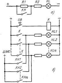 Rice. 4. Control of the serviceability of the warning lamps
To control the serviceability of the signal lamps, two methods are used:
1. constant lighting of the lamp in the absence of a signal, when the signal relay KN is turned off (Fig. 4, a);
2. periodic switching on of the lamps using a control relay (shown in Fig. 4, b of the example of an alarm unit powered by the bus for flashing lights ShMS). To test the lamps, press the SB button. This scheme is usually used with a large number of signal lamps.