Piston control of the movement of the mechanisms
Relay circuits
 In fig. 1 shows various variants of constant stroke piston motion control schemes fixed by the SQ controller.
The diagrams in fig. 1, a-c is used when the cycle consists of one "forward" movement B and one "backward" movement H to the starting position. Schemes 1, a and b are used with an automatic command given by the KQ relay. The KT relay provides a pause before starting reverse. In the diagram of fig. 1, the cycle start command is given by the controller or universal switch SM.
To implement infinite reciprocating motion, the diagram in fig. 1, d. If the number of strokes must be limited by a given value n, an open contact of a counting relay or a unit of several relays, which counts the pulses supplied by the closing contact of the "back" contactor KM2, is included in the contactor circuit « forward» KM1.
An example of implementing a reciprocating motion with variable stroke length in four positions is shown in fig. 2.Contacts SQ.1- SQ.4- of the command device SQ are used to alternatively turn off the mechanism in positions 1—4 of the "forward" stroke, contact SQ.5- in the initial position. The circuit uses pulse commands given by the automation relay KQ1, which is closed, for example, when feeding the workpiece, and KQ2, which fixes the end of the intermediate operation at the end of each stroke.
Sequential maneuvering SQ.1 — SQ.3 of the SQ controller is carried out by contacts of the relay for counting the number of moves of the "back" mechanism KS1, KSZ and KS5. The relay KS7, fixing the fourth move "back", turns off the relay KS1-KC6 and prohibits the next switching on "forward" until the blue arrives at the end of the technological operation with this group of blanks (relay KR). The opening contact of the KR relay in the KC7 coil circuit returns the circuit to its original state.
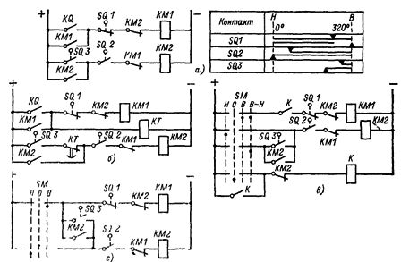
Rice. 1. Relay control circuits for reciprocating movement
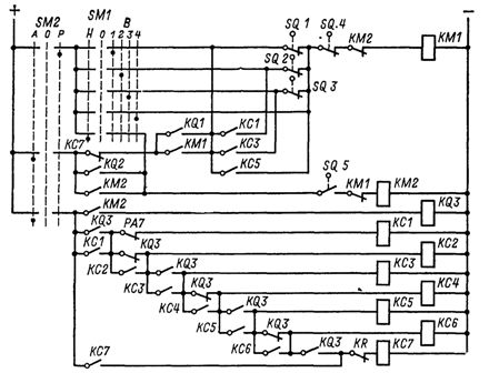
Figure 2. Control scheme of the reciprocating relay with variable stroke length
Logic circuit
The piston movement control circuit made on the elements of the «Logic T» series is shown in fig. 3. Elements D1-D3 of type T-201 are used to coordinate the input relay signals with logic elements.
The memory of the elements D4.1, D4.2 fixes the presence of a command to move "forward" when the relay KQ is switched on pulsed. Through the amplifier D5, the front contactor KM1 is turned on. At the end of the movement of the "forward" mechanism, when the contact of the controller SQ 1 is closed, a signal 1 appears at the output of the corresponding element D2, which turns off the memory D4 and the contactor KM1 and turns on the memory on the elements D6. In this case, the command to move "back" is given and remembered.This command is removed and backward movement is stopped when the contact of the controller SQ 2 closes in the initial position, when signal 1 appears at the output of the corresponding element D3, disabling the memory D6.
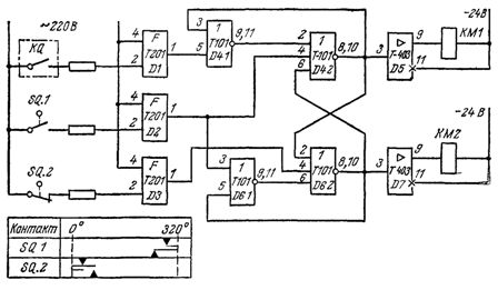
Rice. 3. Scheme for controlling reciprocating movement on elements of the «Logic T» series
Memories D4 and D6 are blocked, so only one of them can be turned on. When memory D4 is on, signal 1 from the output of element D4.2 is fed to input 2 of element D6.2, disabling memory D6 and vice versa. When memory D6 is turned on, signal 1 from the output of element D6 2 is fed to input 6 of element D4.2, disabling memory D4.