Control and power circuits for lifting electromagnets
 Lifting electromagnets have a high inductance, therefore, for quick and complete discharge of the load, as well as for limiting the overvoltage to a value of no more than 2 kV, special circuits and control equipment are used. Electromagnets receive voltage from a motor-generator or rectifier. Schematic control schemes when electromagnets are powered by a direct current network are shown in fig. 1, a and b.
Control lifting electromagnet according to the indicated scheme is carried out in the following way. When the controller K is turned on, voltage is applied to the magnetizing contactor B, the closing contacts of which connect the electromagnet to the network. In this case, the nominal current flows through the coil M of the electromagnet, and the parallel connected discharge resistance (P1 — P4, P4 — PZ and PZ — P2) flows around with a lower value current. The contactor coil H connected between points 6 and 7 does not conduct due to the presence of a series-connected open auxiliary contact B, open when contactor B is on.
When the controller K.is turned off, the closing contacts of the contactor B open, the electromagnet is briefly de-energized and automatically switched to reverse polarity, and after the load drops, the electromagnet is finally disconnected from the power source. This inclusion of the electromagnet provides demagnetization of the load, which contributes to its rapid fall.
The automatic action when the electromagnet is turned off is mainly provided by the operation of the demagnetizing contactor H. The voltage at the terminals of the coil of the contactor H is determined by the voltage drop in the resistance sections 6 — P4 and P4—7. When the electromagnet is turned off, its current does not disappear immediately, but is closed by a circuit of discharge resistances. The resistances of sections 6 — P4 and P4—7 are selected in such a way that after the controller K is turned off and the opening contact B is closed, the contactor H is turned on.
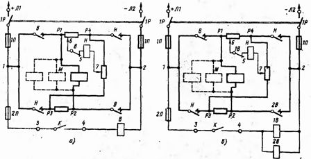
Rice. 1. Schematic control schemes of magnetic controllers PMS 50 (a) and PMS 150 (b) for lifting electromagnets: V or 1V, 2V-bipolar magnetizing contactor or two unipolar; H — two-pole demagnetizing contactor; 1P — switch; 1P, 2P — fuses of the power circuit and the control circuit; K — command controller; M — electromagnet; P1-P4, P4-P3 and P3-P2-discharge resistors.
After switching on the contactor H, its power contacts are closed and the electromagnet is connected to the network. In this case, the direction of the current in the coil of the electromagnet and in the resistance 6-P4 connected in series with the coil changes over time to the opposite. The change in the direction of the current in the section of resistance 6 — P4 occurs with a preliminary reduction of the previous oppositely directed current to zero.At zero current in section 6 — P4, the contactor H remains on because the voltage drop in section P4—7 is sufficient for this (in section 6 — P4, the voltage drop is zero).
When the direction of the current changes in the section 6 — P4, the contactor H is turned off, because its coil turns out to be connected to the difference in the voltage drop in the sections 6 — P4 and P4 — 7. The interruption of the contactor H occurs when the demagnetizing current reaches a value equal to 10-20% of the operating current of the cold coil of the electromagnet, i.e. practically after demagnetization and loss of load.
Once turned off, contactor H disconnects the solenoid coil from the grid, which remains closed to the discharge resistance. This makes it easier to break the arc from the contactor and reduces overvoltage, increasing the life of the coil insulation. The opening auxiliary contact of contactor B (in the coil circuit of contactor H) prevents the simultaneous operation of both contactors.
The circuit allows you to adjust the demagnetization time, which can be done by moving the resistor clamps, that is, by changing the resistance values of sections 6 — P4 and P4—7. At the same time, this time is automatically adjusted depending on the type of load being lifted. With a greater mass of the load, its magnetic conductivity is greater, which leads to an increase in the time constant of the electromagnet and thus to an increase in the demagnetization time. With a light weight of the load, the demagnetization time is reduced.
According to the described scheme, magnetic controllers of types PMS 50, PMS 150, PMS50T and PMS 150T are manufactured.
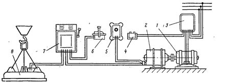
Rice. 2.Electric circuit of the lifting electromagnet of the crane in the presence of an alternating current network: 1 — asynchronous electric motor; 2 — adequate current generator; 3 — magnetic starter; 4 — control button; 5 — excitation regulator; 6 — command controller; 7 — magnetic controller; 8 — lifting electromagnet.
Most cranes with lifting solenoids are AC mains powered, so a motor generator or rectifier must be used for DC solenoids. In fig. 2 shows the supply circuit of the lifting electromagnet from the motor-generator. Generator protection against short circuit currents. a voltage relay of the REV 84 type is conducted in the cable feeding the electromagnet.
Replacing rotary converters with static converters reduces capital costs, electrical weight and operating costs. The PSM 80 type magnetic controller in combination with the KP 1818 selsyn control controller enables load capacity adjustment. This is of great importance in works related to finishing, sorting, marking and transportation of sheet metal in metallurgical plants, as well as in various warehouses and bases.
In fig. 3 shows a diagram of a magnetic controller PSM 80 with a statically controlled converter. The converter is made according to a transformerless three-phase full-wave circuit with one thyristor and a discharge diode. Current regulation is carried out by changing the output voltage of the converter by changing the opening angle of the thyristor. The opening angle of the thyristor depends on the reference signal, which is infinitely adjustable over a wide range by the synchronous control controller.
Supply I uses a three-winding transformer.The 36 V winding is used to power the relay elements, the selsin excitation voltage of the controller is removed from the 115 V winding. The power supply includes a single-phase rectifier D7-D10, at the output of which zener diodes St1-St3 and a ballast resistor R2 are installed.
The stabilized supply voltage of the relay element 16.4 V is removed by the zener diodes St2 and St3. In this case, a forward current flows through the resistor R3 and the base of the transistor T1, which turns on the transistor. From the zener diode St1, a negative bias (-5.6 V) is applied to the base of transistor T2 to turn it off when transistor T1 is open.
Block task II consists of Selsinaincluded in the selsyny controller and single-phase rectifier D11-D14. The line voltage of the selsyn rotor is applied to the bridge input, which changes as it rotates relative to the stator. The rotor is rotated by the handle CCK. At the output of the bridge, a changing rectified voltage is obtained, in proportion to which the output current that flows when the transistor T1 is open, through its base and resistor R6, also changes. The relay element is assembled on two p-p-p type transistors.
To provide phase control mode in the circuit, a sawtooth voltage source is provided, which is an RC circuit, which is shunted by the thyristor T. While the thyristor is closed, the capacitors C4 C5 are charged. When the thyristor T opens, a rapid discharge of the capacitors occurs. The saw current flows through resistor R13 and the base of transistor T1.
The selsinki controller has one fixed position (zero) and provides a brake condition at any intermediate position of the control handle.In this case, a certain value of the electromagnetic current corresponds to each position of the rotor selsyn. In the control positions, the circuit maintains with sufficient accuracy the average value of the electromagnet current when its coil is heated. The tolerances of current for cold and hot coil do not exceed 10%, and the maximum value of current for heated coil does not exceed the catalog value of current by more than 5. When the supply voltage fluctuates in the range (0.85 — 1.05) UH, the change in current of the electromagnet does not exceed the specified limits.
The DC side switching circuit includes:
• two-pole contactors for direct KB and reverse CV electromagnet switching;
• two time relays РВ and РП to control the demagnetization process of the electromagnet during shutdown,
• discharge resistors R19 — R22 to limit the overvoltage that occurs when the electromagnet is turned off;
• diode D4 to reduce the power of the discharge resistors.
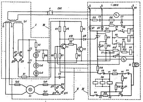
Rice. 3. Scheme for adjusting the load-carrying capacity of the electromagnet: I - power supply block: II - task block; III — relay element; VI — power circuit; R1 — R25 — resistors; C1 — C8 — capacitors, W — shunt; VA — automatic switch; D1 -D16 — diodes; KV and KN — contactors with direct and reverse winding of an electromagnet (magnetization and demagnetization); РВ and РП — time relay for controlling the demagnetization process, Pr1 — Pr4 — fuses; Сс — controller selsyn; St1 -St3 — zener diodes; T — thyristor: T1, T2 — transistors, TP1 — transformer; EM — lifting electromagnet; SKK — selsyn control controller.
If the cable feeding the electromagnet breaks, it is necessary to turn off the switch or circuit breaker of the magnetic controller. It is strictly forbidden to be under a faucet with a working electromagnet. Inspection and replacement of devices must be carried out with the main switch of the faucet turned off.
All electrical devices must be securely grounded. Pay special attention to the grounding of the electromagnet. The ground bolt in the solenoid box is connected to the ground bolt of the magnetic controller cabinet. The connection is made from one of the cores of the three-core power cable. Otherwise, the operation of electrical equipment should be guided by the general safety rules for servicing electrical installations.