Thyristor electric drive
 In industry, actuators with controlled semiconductor valves - thyristors - are widely used. Thyristors are manufactured for currents up to hundreds of amperes, for voltages up to 1000 volts or more. They are distinguished by high efficiency, relatively small size, high speed and the ability to work in a wide range of ambient temperatures (from -60 to +60 ° C).
The thyristor is not a fully controllable device, which is turned on by applying the corresponding potential to the control electrode, and is turned off only by forced interruption of the current circuit due to interruption voltage, its natural transition through zero or supply of a damping voltage of the opposite sign. By changing the timing of the supply of the control voltage (its delay), you can adjust the average value of the rectified voltage and thus the speed of the motor.
The average value of the rectified voltage in the absence of regulation is mainly determined by the switching circuit of the thyristor converter. Transducer circuits are divided into two classes: zero-pull and bridged.
In medium and high power installations, bridge converter circuits are mainly used, which mainly for two reasons:
-
less voltage on each of the thyristors,
-
absence of a constant current component flowing through the transformer windings.
Converter circuits can also differ in the number of phases: from one in low-power installations to 12 — 24 in powerful converters.
All variants of thyristor converters along with positive properties, such as low inertia, lack of rotating elements, smaller (compared to electromechanical converters) in size, have a number of disadvantages:
1. Hard connection to the network: all voltage fluctuations in the network are transmitted directly to the drive system and the load increases, the motor axes are immediately transferred to the network and cause current shocks.
2. Low power factor when adjusting the voltage down.
3. Generation of higher harmonics, load on the power grid.
Mechanical characteristics of a motor driven by a thyristor converter is determined by the voltage applied to the armature and the nature of its change with the load, that is, the external characteristics of the converter and the parameters of the converter and the motor.
The device and principle of operation of the thyristor
A thyristor (Fig. 1, a) is a four-layer silicon semiconductor with two pn-junctions and one n-p-junction. The magnitude of the current Azpassing through the thyristor under the action of the anode voltage Ua depends on the current Azduring the control passing through the control electrode under the action of the control voltage Uy.
If there is no control current (Azy = 0), then as the voltage U increases, the current A in the circuit of the user P will increase, however, remaining a very small value (Fig. 1, b).

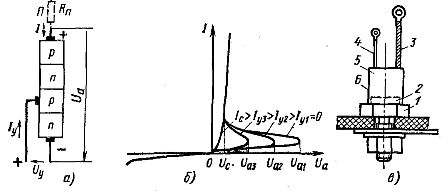
Rice. 1. Block diagram (a), current-voltage characteristic (b) and construction (c) of the thyristor
At this time, the n-p junction turned on in the non-conducting direction has a high resistance. At a certain value Ua1 of the anode voltage, called the opening, ignition or switching voltage, an avalanche breakdown of the blocking layer occurs. Its resistance becomes small and the current strength increases to a value determined in accordance with Ohm's law by the resistance Rp of the user P.
As the current Iу increases, the voltage Ua decreases. The current Iu, at which the voltage Ua reaches the lowest value, is called the current I with correction.
The thyristor closes when the voltage Ua is removed or when its sign changes. The rated current I of the thyristor is the largest average value of the current flowing in the forward direction that does not cause unacceptable overheating.
Nominal voltage Un is called the highest permissible amplitude voltage at which the given reliability of the device is ensured.
The voltage drop ΔUncreated by the nominal current is called the nominal voltage drop (usually ΔUn = 1 — 2 V).
The value of the current strength Ic of the correction fluctuates within the limits of 0.1 — 0.4 A at a voltage Uc 6 — 8 V.
The thyristor reliably opens with a pulse duration of 20 — 30 μs. The interval between pulses should not be less than 100 μs. When the voltage Ua drops to zero, the thyristor turns off.
The external design of the thyristor is shown in fig.1, v… Copper-based 1 sixteenth silicon four-layer structure 2 with threaded tail, with negative power 3 and control of 4 outputs. The silicon structure is protected by a cylindrical metal housing 5. The insulator is fixed in the housing 6. A thread in the base 1 is used to install a thyristor and to connect the anode voltage source to the positive pole.
As the voltage Ua increases, the control current required to open the thyristor decreases (see Fig. 1, b). The control opening current is proportional to the control opening voltage uyo.
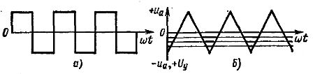
If Uа changes according to the sinusoidal law (Fig. 2), then the required voltage and 0 opening can be depicted by a dotted line. If the applied control voltage Uy1 is constant and its value is below the minimum value of the voltage uuo, then the thyristor does not open.
If the control voltage is increased to the value Uy2, the thyristor will open as soon as the voltage Uy2 becomes greater than the voltage uyo. By changing the uу value, you can change the opening angle of the thyristor in the range from 0 to 90°.
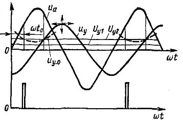
Rice. 2. Thyristor control
To open the thyristor at angles above 90 °, a variable control voltage uy is used, which changes, for example, sinusoidally. At a voltage corresponding to the intersection of the sine wave of this voltage with the dotted curve uuo = f (ωt), the Tiristor opens.
By moving the sinusoid uyo horizontally to the right or left, you can change the angle ωt0 opening of the thyristor. This opening angle control is called horizontal. It is carried out using special phase switches.
By moving the same sine wave vertically up or down, you can also change the opening angle. Such management is called vertical. In this case, with variable voltage control tyy, add a constant voltage algebraically, for example, the voltage Uy1... The opening angle is adjusted by changing the magnitude of this voltage.
Once opened, the thyristor remains open until the end of the positive half-cycle and the control voltage does not affect its operation. This also makes it possible to apply pulse control by periodically applying positive control voltage pulses at the right time (Fig. 2 bottom). This increases the clarity of the control.
By changing the opening angle of the thyristor in one way or another, voltage pulses of different shapes can be applied to the user. This changes the value of the average voltage at the user's terminals.
Various devices are used to control thyristors. In the scheme shown in fig. 3, the AC mains voltage is applied to the primary winding of the transformer Tp1.
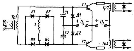
Rice. 3. Thyristor control circuit
A full wave rectifier B is included in the secondary circuit of this transformer.1, B2, B3, B4 with a significant inductance L in the DC circuit. The practical wave current is practically eliminated. But such a direct current can only be obtained by full-wave rectification of an alternating current having the form shown in Fig. 4, a.
Thus, in this case, the rectifier B1, B2, B3, B4 (see Fig. 3) is a converter in the form of alternating current. In this scheme, capacitors C1 and C2 alternate in series with rectangular current pulses (Fig. 4, a).In this case, on the plates of the capacitors C1 and C2 (Fig. 4, b), a transverse sawtooth voltage is formed, applied to the bases of the transistors T1 and T2 (see Fig. 3).
This voltage is called the reference voltage. The DC voltage Uy also acts in the main circuit of each transistor. When the saw voltage is zero, the voltage Uy creates positive potentials at the bases of both transistors. Each transistor opens with a base current at a negative base potential.
This happens when the negative values of the saw reference voltage turn out to be greater than Uy (Fig. 4, b). This condition is fulfilled depending on the value of Uy at different values of the phase angle. In this case, the transistor opens for different periods of time, depending on the magnitude of the voltage Uy.
Rice. 4. Diagrams of thyristor control voltages
When one or the other transistor opens, a rectangular current pulse passes through the primary winding of the transformer Tr2 or Tr3 (see Fig. 3). When the leading edge of this pulse passes, a voltage pulse occurs in the secondary winding, which is applied to the control electrode of the thyristor.
When the back of the current pulse passes through the secondary winding, a voltage pulse of opposite polarity occurs. This pulse is closed by a semiconductor diode that bypasses the secondary winding and is not applied to the thyristor.
When the thyristors are controlled (see Fig. 3) with two transformers, two pulses are generated, phase shifted by 180 °.
Thyristor motor control systems
In thyristor control systems for DC motors, a change in the DC armature voltage of the motor is used to control its speed. In these cases, multiphase rectification schemes are usually used.
In fig. 5, and the simplest diagram of this kind is shown with a solid line. In this circuit, each of the thyristors T1, T2, T3 is connected in series with the secondary winding of the transformer and the motor armature; NS. etc. c. the secondary windings are out of phase. Therefore, voltage pulses that are phase-shifted relative to each other are applied to the motor armature when controlling the opening angle of the thyristors.
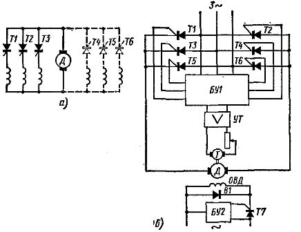
Rice. 5. Thyristor drive circuits
In a polyphase circuit, intermittent and continuous currents can pass through the armature of the motor, depending on the selected firing angle of the thyristors. A reversible electric drive (Fig. 5, a, the entire circuit) uses two sets of thyristors: T1, T2, T3 and T4, T5, T6.
By opening the thyristors of a certain group, they change the direction of the current in the armature of the electric motor and, accordingly, the direction of its rotation.
Reversing the motor can also be achieved by changing the direction of the current in the field winding of the motor. Such a reverse is used in cases where high speed is not required because the field winding has a very high inductance compared to the armature winding. Such a reverse stroke is often used for thyristor drives of the main motion of metal cutting machines.
The second set of thyristors also makes it possible to perform braking modes requiring a change in the direction of the current in the armature of the electric motor.Thyristors in the drive circuits under consideration are used to turn the motor on and off, as well as to limit the starting and braking currents, eliminating the need to use contactors, as well as starting and braking rheostats.
In DC thyristor drive circuits, power transformers are undesirable. They increase the size and cost of the installation, so they often use the circuit shown in Fig. 5 B.
In this circuit, the ignition of the thyristor is controlled by the control unit BU1. It is connected to a three-phase current network, thereby providing power and matching the phases of the control pulses with the anode voltage of the thyristors.
A thyristor drive usually uses motor speed feedback. In this case, a tachogenerator T and an intermediate transistor amplifier UT are used. Email feedback is also used. etc. c. electric motor, realized by simultaneous action of negative feedback on voltage and positive feedback on armature current.
To adjust the excitation current, a thyristor T7 with a control unit BU2 is used. At negative half-cycles of the anode voltage, when the thyristor T7 does not pass current, the current in the OVD continues to flow due to e. etc. c. self-induction, closing through the bypass valve B1.
Thyristor electric drives with pulse width control
In the considered thyristor drives, the motor is powered by voltage pulses with a frequency of 50 Hz. To increase the response speed, it is recommended to increase the pulse frequency.This is achieved in thyristor drives with pulse width control, where rectangular DC pulses of varying duration (latitude) with a frequency of up to 2-5 kHz pass through the motor armature. In addition to high-speed response, such control provides large motor speed control ranges and higher energy performance.
With pulse width control, the motor is powered by an uncontrolled rectifier, and the thyristor connected in series with the armature is periodically closed and opened. In this case, the DC pulses pass through the armature circuit of the motor. A change in the duration (latitude) of these pulses results in a change in the speed of rotation of the electric motor.
Since in this case the thyristor operates at constant voltage, special circuits are used to close it. One of the simplest pulse width control schemes is shown in Fig. 6.
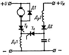
Rice. 6. Thyristor electric drive with pulse width control
In this circuit, the thyristor Tr is turned off when the damping thyristor Tr is turned on. When this thyristor opens, the charged capacitor C discharges to throttle Dr1, creating a significant e. etc. c. In this case, a voltage appears at the ends of the choke, which is greater than the voltage U of the rectifier and directed towards it.
Through a rectifier and shunt diode D1, this voltage is applied to the thyristor Tr and causes it to turn off. When the thyristor is turned off, the capacitor C is charged again to the switching voltage Uc > U.
Due to the increased frequency of current pulses and the inertia of the motor armature, the pulse nature of the power supply is practically not reflected in the smoothness of the motor rotation. The thyristors Tr and Tr are opened by a special phase shift circuit that allows the pulse width to be changed.
The electrical industry produces various modifications of fully regulated thyristor DC power drives. Among them are drives with 1:20 speed control ranges; 1: 200; 1: 2000 by changing the voltage, irreversible and reversible drives, with and without electric braking. Control is carried out by means of transistor phase-pulse devices. Drives use negative feedback on motor rpm and e. counter etc. with
The advantages of thyristor drives are high energy characteristics, small size and weight, the absence of any rotating machinery other than an electric motor, high speed and constant readiness for work. The main disadvantage of thyristor drives is their still high cost, which significantly exceeds the cost of drives with an electric machine and magnetic amplifiers.
Currently, there is a steady trend towards widespread replacement of thyristor DC drives with variable frequency AC drives.