Stepper motor control
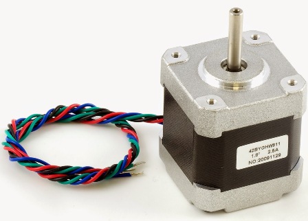
Electric motors convert electrical energy into mechanical energy, and as for stepper motors, they convert the energy of electrical impulses into rotary movements of the rotor. The motion generated by the action of each pulse is initiated and repeated with high precision, making ball motors efficient drives for devices that require precise positioning.
Permanent magnet stepper motors include: a permanent magnet rotor, stator windings and a magnetic core. The energy coils create magnetic north and south poles as shown. The moving magnetic field of the stator forces the rotor to align with it at all times. This rotating magnetic field can be tuned by controlling the series excitation of the stator coils to turn the rotor.
The figure shows a diagram of a typical excitation method for a two-phase motor. In phase A the two stator coils are energized and this causes the rotor to attract and lock as the opposite magnetic poles attract each other.When the windings of phase A are turned off, the windings of phase B are turned on, the rotor rotates clockwise (English CW — clockwise, CCW — counterclockwise) 90 °.
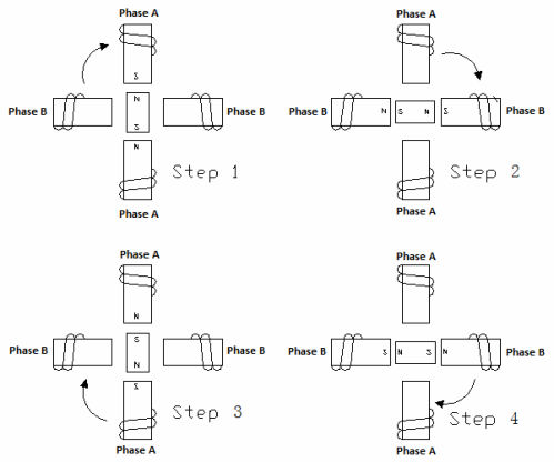
Then phase B turns off and phase A turns on, but the poles are now opposite to what they were at the very beginning. This leads to the next 90 ° turn. Phase A is then switched off, phase B is switched on with reverse polarity. Repeating these steps will cause the rotor to rotate clockwise in 90° increments.
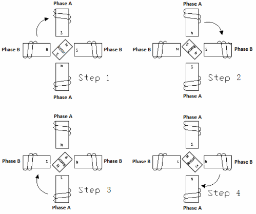
The stepwise control shown in the figure is called single-phase control. A more acceptable way of stepping control is two-phase active control, where both phases of the motor are always on, but the polarity in one of them changes, as shown in the figure.
This control causes the rotor of the stepper motor to move so that it aligns with each step at the center of the formed north and south poles, between the magnetic circuit protrusions. Because both phases are always on, this control method provides 41.4% more torque than control with one active phase, but requires twice the electrical power.
Half a step
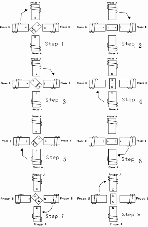
A stepper motor can also be "semi-stepped", then a tripping stage is added during the phase transition. This cuts the pitch angle in half. For example, instead of 90 °, a stepper motor can make 45 ° rotations on each «half step», as shown in the figure.
But the half step mode introduces a torque loss of 15-30%, compared to the step control with two active phases, because one of the windings is inactive during half of the step and this ultimately leads to a loss of electromagnetic force , acting on the rotor, i.e. net torque loss.
Bipolar coil
Two-phase step control assumes the presence of a two-pole stator winding. Each phase has its own coil, and when the current is reversed through the coils, the electromagnetic polarities also change. The initial stage is typical two-phase driver shown in the figure. The control scheme is shown in the table. It can be seen how simply by changing the direction of the current through the coils it is possible to change the magnetic polarity in the phases.
Single pole coil
Another typical type of coil is a unipolar coil. Here the coils are divided into two parts and when one part of the coil is energized, a north pole is created, when the other part is energized, a south pole is created. This solution is called a unipolar coil because the electrical polarity responsible for the current never changes. The control stages are shown in the figure.
This design allows a simpler electronic block to be used. However, almost 30% of the torque is lost here compared to a bipolar coil because the coils have half the wire as a bipolar coil.
Other tilt angles
To obtain smaller pitch angles, it is necessary to have a larger number of poles on both the rotor and the stator. The 7.5° rotor has 12 pole pairs and the stator magnetic core has 12 protrusions. Two bobbin ears and two coils.
This gives 48 poles for each step of 7.5°. In the figure you can see the 4-pole lugs in section. It is of course possible to combine the steps to achieve large displacements, for example six steps of 7.5° will result in a rotor rotation of 45°.
Accuracy
The accuracy of stepper motors is 6-7% per step (without accumulation). A stepper motor with 7.5° steps will always be within 0.5° of the theoretically predicted position, no matter how many steps have already been taken. The error will not accumulate because mechanically every 360 ° is repeated step by step. With no load, the physical position of the stator and rotor poles relative to each other will be the same at all times.
Resonance
Stepper motors have their own resonant frequency because they are spring weight like systems. When the rhythm is the same as the natural resonance frequency of the motor, the noise generated by the motor can be heard and the vibration is amplified.
The resonance point depends on the motor application, its load, but generally the resonance frequency ranges from 70 to 120 steps per second. In the worst case, the motor will lose control accuracy if it goes into resonance.
An easy way to avoid system resonance problems is to change the rhythm away from the resonance point. In half or micro-step mode, the resonance problem is reduced because the resonance point is abandoned as the speed increases.
Torque
The torque of a stepper motor is a function of: step speed, stator winding current, motor type. The power of a particular stepper motor is also related to these three factors.The torque of a stepper motor is the sum of the frictional torque and the inertial torque.
The frictional torque in grams per centimeter is the force required to move a load weighing a certain number of grams with a lever arm 1 cm long. It is important to note that as the step speed of the motor increases, the back EMF in the motor, that is, the voltage generated by the motor increases. This limits the current in the stator windings and reduces the torque.