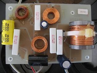
AC inductor
Consider a circuit containing an inductor and suppose that the resistance of the circuit, including the coil wire, is so small that it can be neglected. In this case, connecting the coil to a source of direct current would result in a short circuit, in which, as is known, the current in the circuit would be very large.
The situation is different when the coil is connected to an AC source. In this case, no short circuit occurs. This shows. What does an inductor resist to alternating current passing through it.
What is the essence of this resistance and how is it conditioned?
To answer this question, remember phenomenon of self-induction… Any change in current in the coil causes an EMF of self-induction to appear in it, which prevents a change in current. The value of EMF of self-induction is directly proportional to the inductance value of the coil and the rate of change of the current in it. But since alternating current changes continuously The electromagnetic radiation for self-induction that continuously appears in the coil creates resistance to alternating current.
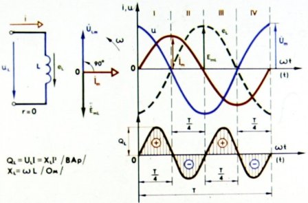
To understand the processes taking place in alternating current circuits with the inductor, see the graph.Figure 1 shows curved lines that characterize, respectively, the mark in the circuit, the voltage in the coil and the emf of self-induction occurring in it. Let's make sure that the constructions made in the figure are correct.
AC circuit with an inductor
From the moment t = 0, that is, from the initial moment of observing the current, it begins to increase rapidly, but as it approaches its maximum value, the rate of increase of the current decreases. At the moment when the current reached its maximum value, the rate of its change momentarily became equal to zero, that is, the current change stopped. Then the current initially started slowly and then quickly decreased, and after the second quarter of the period it dropped to zero. The rate of change of the current during this quarter of the period, increasing from the bullet, reaches the highest value when the current becomes equal to zero.
Figure 2. The nature of changes in the current over time, depending on the magnitude of the current
From the constructions in Figure 2, it can be seen that when the current curve passes through the time axis, the current increases in a short time period T more than in the same time period when the current curve reaches its peak.
Therefore, the rate of change of the current decreases as the current increases and increases as the current decreases, regardless of the direction of the current in the circuit.
It is obvious that the emf of the self-inductance in the coil must be greatest when the rate of change of current is greatest, and decrease to zero when its change ceases. In fact, on the graph, the EMF curve of self-induction eL in the first quarter of the period, starting from the maximum value, it fell to zero (see Fig. 1).
During the next quarter of the period, the current from the maximum value decreases to zero, but the rate of its change gradually increases and is greatest at the moment when the current is equal to zero. Accordingly, the EMF of the self-induction during this quarter of the period, appearing again in the coil, gradually increases and turns out to be a maximum until the current becomes equal to zero.
However, the direction of self-induction emf changed in the opposite direction, as the increase in current in the first quarter of the period was replaced in the second quarter by its decrease.
Circuit with inductance
Continuing further the construction of the curve of EMF of self-induction, we are convinced that during the period of change of current in the coil and EMF of self-induction in it will complete a full period of its change. Its direction is determined Lenz's law: with an increase in the current, the emf of self-induction will be directed against the current (the first and third quarter of the period), and with a decrease in the current, on the contrary, it coincides with it in direction (the second and fourth quarter of the period).
Therefore, the EMF of self-induction caused by the alternating current itself prevents it from increasing, and, on the contrary, it maintains it when descending.
Let us now turn to the coil voltage graph (see Fig. 1). In this graph, the sine wave of the coil terminal voltage is shown equal and opposite to the sine wave of the self-inductance emf. Therefore, the voltage at the terminals of the coil at any instant of time is equal and opposite to the EMF of self-induction arising in it. This voltage is created by an alternator and goes to quench the action in the EMF self-induction circuit.
Therefore, in an inductor connected to an AC circuit, resistance is created when current flows. But since such resistance eventually induces inductance of the coil, then it is called inductive resistance.
Inductive resistance is denoted by XL and is measured, as a resistance, in ohms.
The inductive resistance of the circuit is the greater, the greater current source frequencycircuit supply and greater circuit inductance. Therefore, the inductive resistance of a circuit is directly proportional to the frequency of the current and the inductance of the circuit; is determined by the formula XL = ωL, where ω — circular frequency determined by the product 2πe… — circuit inductance in n.
Ohm's Law for an AC circuit containing an inductive resistance sounds Thus: the amount of current is directly proportional to the voltage and inversely proportional to the inductive resistance of NSi, i.e. I = U / XL, where I and U are the effective current and voltage values, and xL is the inductive resistance of the circuit.
Considering the graphs of the change of current in the coil. EMF of self-induction and voltage at its terminals, we paid attention to the fact that the change in them vValues do not coincide in time. In other words, the current, voltage and self-induction EMF sinusoids turned out to be time-shifted relative to each other for the circuit under consideration. In AC technology, this phenomenon is commonly called phase shift.
If two variable quantities change according to the same law (in our case sinusoidal) with the same periods, simultaneously reach their maximum value in both forward and reverse directions, and also simultaneously decrease to zero, then such variable quantities have the same phases or, as they say, match in phase.
As an example, Figure 3 shows phase-matched current and voltage curves. We always observe such phase matching in an AC circuit consisting only of active resistance.
In the case where the circuit contains inductive resistance, current and voltage phases, as seen in Fig. 1 do not match, that is, there is a phase shift between these variables. The current curve in this case seems to lag behind the voltage curve by a quarter of the period.
Therefore, when an inductor is included in an AC circuit, a phase shift between current and voltage occurs in the circuit, and the current lags the voltage in phase by a quarter of the period... This means that the maximum current occurs a quarter of the period after reaching the maximum voltage.
The EMF of the self-induction is in antiphase with the voltage of the coil, lagging behind the current by a quarter of the period. In this case, the period of change of the current, the voltage, as well as the EMF of the self-induction does not change and remains equal to the period of change of the voltage of the generator feeding the circuit. The sinusoidal nature of the change in these values is also preserved.
Figure 3. Phase matching of current and voltage in an active resistance circuit
Let us now understand the difference between an alternator load with active resistance and load with its inductive resistance.
When an AC circuit contains only one active resistance, then the energy of the current source is absorbed in the active resistance, heating the wire.
When the circuit does not contain active resistance (we usually consider it zero), but consists only of inductive resistance of the coil, the energy of the current source is spent not on heating the wires, but only on creating an EMF of self-induction, that is, it becomes the energy of the magnetic field ... The alternating current, however, is constantly changing both in magnitude and direction, and therefore, magnetic field the coil is continuously changing in time with the current changing. During the first quarter of the period, when the current is increasing, the circuit receives energy from the current source and stores it in the magnetic field of the coil. But as soon as the current, having reached its maximum, begins to decrease, it is maintained at the expense of the energy stored in the magnetic field of the coil by the emf of self-induction.
Therefore, the current source, having given some of its energy to the circuit in the first quarter of the period, receives it back from the coil in the second quarter, which acts as a kind of current source. In other words, an AC circuit containing only inductive resistance consumes no energy: in this case, there is an energy fluctuation between the source and the circuit. Active resistance, on the contrary, absorbs all the energy transferred to it from the current source.
An inductor, unlike an ohmic resistance, is said to be inactive with respect to an AC source, i.e. reactive... Therefore, the inductive resistance of the coil is also called reactance.
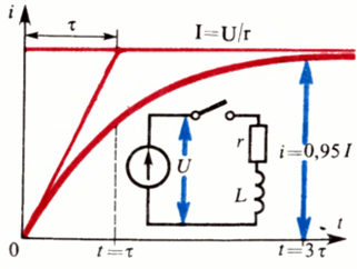
Current rise curve when closing a circuit containing an inductance — transients in electrical circuits.
Earlier on this thread: Electricity for dummies / Fundamentals of electrical engineering
What are others reading?
# 1 wrote: Alexander (March 4, 2010 5:45 PM)
is the current in phase with the generator emf? And its value decreases?
#2 wrote: administrator (Mar 7, 2010 4:35 pm)
In an AC circuit consisting of only active resistance, the current and voltage phases match.
# 3 wrote: Alexander (March 10, 2010 09:37)
Why is the voltage equal and opposite to the EMF of the self-induction, after all, at the moment when the EMF of the self-induction is maximum, the EMF of the generator is equal to zero and cannot create this voltage? Where does (the tension) come from?
* In a circuit with only one inductor that has no active resistance, is the current flowing through the circuit in phase with the generator emf (the emf which depends on the frame position (in a regular generator), not the generator voltage)?