The principle of operation and purpose of HF communication channels of high-voltage power lines
 Link — a set of devices and physical media that transmit signals. With the help of channels, signals are transmitted from one place to another, and also transferred in time (when storing information).
The most common devices that make up a channel are amplifiers, antenna systems, switches and filters. A pair of wires, a coaxial cable, a waveguide, a medium in which electromagnetic waves propagate are often used as a physical medium.
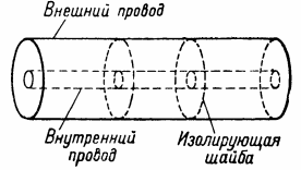
Coaxial cable — a high-frequency cable in which one of the conductors is a hollow tube that completely encloses the second conductor. The inner wire is located exactly along the axis of the pipe, which is why the cable is called coaxial or concentric. To keep the inner wire in this position, either the space between the outer and inner wires is completely filled with insulating material, or individual insulators are placed over the inner wire.
Since in a coaxial cable all electric and magnetic fields are concentrated in the space between the outer and inner conductors, i.e. there are no external fields, radiation losses are negligible. To reduce losses when heating the metal, the inner wire can be made with a large diameter (the surface of the outer wire in any case is large enough).
If the coaxial cable is to be flexible, then its outer conductor is made in the form of a flexible metal braid and the cable is filled with plastic insulating material.
In terms of communication technology the most important characteristics of communication channels are the distortions to which the signals transmitted over it are subjected. Distinguish between linear and non-linear distortions. Linear distortion consist of frequency and phase distortions and are described by the transient response or, equivalently, by the complex gain of the channel. Nonlinear distortion are given by nonlinear dependencies that show how the signal changes as it travels through the communication channel.
A communication channel is characterized by a collection of signals that are sent at the transmitting end and signals that are received at the receiving end. In case the channel input and output signals are functions defined on a discrete set of argument values, the channel is called separated… Such communication channels are used, for example, in pulsed modes of operation of transmitters, in telegraphy, telemetry and radar.
Continuously is called a channel whose output and input signals are continuous functions. Such channels are widely used in telephony, radio broadcasting, television.Discrete and continuous communication channels are also widely used in automation and telemechanics.
Several different channels can share the same technical connection. In these cases (for example, in multi-channel communication lines with frequency or time division signals), the channels are combined and disconnected using special switches or filters. Sometimes, on the contrary, one channel uses several technical communication lines.
High-frequency communication (HF communication) is a type of communication in electrical networks, which provides for the use of high-voltage power lines as communication channels. An alternating current with a frequency of 50 Hz flows through the wires of the power line of the electrical networks. The essence of the organization of HF communication is that the same wires are used as signal transmission on the line, but with a different frequency.
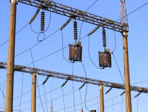
The frequency range of HF communication channels is from tens to hundreds of kHz. High-frequency communication is organized between two neighboring substations, which are connected by a power line with a voltage of 35 kV and more. To alternating current with a frequency of 50 Hz reached the busbars of the substation switchgear, and the communication signals to the respective communication sets use high-frequency suppressors and communication capacitors.
An HF trap has a small current resistance at the industrial frequency and a high resistance at the frequency of high-frequency communication channels. A coupling capacitor — on the contrary: it has a high resistance at a frequency of 50 Hz, and a low resistance at the frequency of the communication channel.This ensures that only 50 Hz current flows to the substation buses and only high frequency signals to the HF communication set.
To receive and process HF communication signals, special filters, signal transceivers and sets of equipment that perform certain functions are installed at both substations, between which HF communication is organized. Below we will consider which functions can be implemented using HF communication.
The most important function is the use of the HF channel in devices for relay protection and automation of substation equipment. The HF communication channel is used for protection of 110 and 220 kV lines-phase-differential protection and directional high-frequency protection. Protection sets are installed at both ends of the transmission line, which are interconnected by an RF communication channel. Due to their reliability, speed and selectivity, protection using a HF communication channel is used as the main one for every 110-220 kV overhead line.
A signal transmission channel for relay protection of power lines (PTL) is called a relay protection channel... Three types of HF protection are most widely used in relay protection technology:
-
directional filter,
-
remote with HF blocking,
-
differential phase.
In the first two types of protection, a continuous HF blocking signal is transmitted through the HF channel with an external short circuit, in phase differential protection, the HF voltage pulses are transmitted through the relay protection channel. The duration of pulses and pauses is approximately the same and is equal to half the period of the supply frequency.In the event of an external short circuit, the transmitters located at both ends of the line operate in different half-cycles of the supply frequency. Each of the receivers receives signals from both transmitters. As a result, in the event of an external short circuit, both receivers receive a continuous blocking signal.
In the event of a short circuit on the protected line, a phase shift of the manipulation voltages occurs and time intervals occur when both transmitters are stopped. In this case, an interrupting current appears in the receiver, which is used to create a signal that acts to open the circuit breaker at that end of the protected line.
Normally, the transmitters at both ends of the line operate on the same frequency. However, on long-distance lines there are sometimes relay protection channels with transmitters operating at different HF or at closely spaced frequencies (1500-1700 Hz). Working on two frequencies makes it possible to get rid of the harmful effects of signals reflected from the opposite end of the line. Protective relay channels use a special (dedicated) RF channel.
There are also devices that use a high-frequency communication channel to determine the location of power line damage. In addition, the RF communication channel can be used to transmit signals telemechanical equipment, SCADA, ACS and other APCS equipment systems.Thus, through the high-frequency communication channel, it is possible to control the operation mode of the substation equipment, as well as to transmit commands to control switches and various functions. relay protection devices.
Another function is a telephone function… HF channel can be used for operational negotiation between neighboring substations. In modern conditions, this function is not relevant, since there are more convenient ways of communication between the service personnel of the facilities, but the HF channel can serve as a backup communication channel in the event of an emergency, when there will be no mobile or landline telephone communication .
Power line communication channel — a channel used to transmit signals in the 300 to 500 kHz range. Different schemes are used to turn on the equipment of the communication channel. Along with the phase-ground circuit (Fig. 1), which is the most common due to its economy, the following circuits are used: phase-phase, phase-two-phase, two-phase-ground, three-phase-ground, phase-phase of different lines. The high-frequency trap, coupling capacitor, and coupling filter used in these circuits are powerline processing equipment for organizing high-frequency communication channels along their wires.
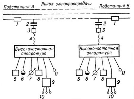
Rice. 1. Block diagram of a simple communication channel through a power transmission line between two adjacent substations: 1 — HF trap; 2 — coupling capacitor; 3 — connecting filter; 4 — HF cable; 5 — device TU — TS; c — telemetry sensors; 7 — telemetry receivers; 8 — devices for relay protection and / or tele-automation; 9 — automatic telephone switchboard; 10 — ATS subscriber; 11 — direct subscribers.
Linear processing is necessary to obtain a stable communication channel. The attenuation of the HF channel through the redesigned power lines is almost independent of the line switching scheme.In the absence of processing, communication will be interrupted when the ends of the transmission line are disconnected or grounded. One of the most important problems of communication on power lines is the lack of frequencies due to the low voltage between the lines that are connected through the substation busbars.
HF channels can be used to communicate with on-site crews repairing damaged power lines and troubleshooting electrical installations. Special portable transmitters are used for this purpose.
The following HF equipment connected to the converted power line is used:
-
combined equipment for telemechanics, automation, relay protection and telephone channels;
-
specialized equipment for any of the listed functions;
-
long-distance communication equipment connected to the power line through the connecting device directly or with the help of additional units to shift the frequency and increase the transmission level;
-
line impulse control equipment.