Non-contact sensors for the position of mechanisms
 In this article we will talk about position sensors of mechanisms. Basically, the main function of any sensor is to give a signal when a specific event occurs. That is, when a trigger event occurs, the sensor is activated and generates a signal, which can be analog or discrete, digital.
Limit sensors have been used as position sensors for many decades. switches. They consist of electrical contacts that mechanically open or close when some variable (position) reaches a certain value. Limit switches of various types are an important part of many control systems, the reliability of which depends on them. such sensors contain moving mechanical elements whose resources are limited.
Limit switches are currently being actively replaced by various proximity sensors. Most often proximity sensors of the following types: inductive, generator, magnetohercon and photoelectronic. These sensors have no mechanical contact with the moving object whose position is being monitored.
Non-contact position sensors ensure high speed and high frequency of switching on the mechanism. A certain disadvantage of these sensors is the dependence, their accuracy, on changes in supply voltage and temperature. Depending on the requirements, the output device of these devices can be as follows contactless logic elementand electrical relay.
In precision braking schemes of electric drives, proximity sensors can be used both to command a downshift and a final stop.
There are many types of sensors on the market today, but within the framework of this article we will highlight the topic directly inductive position sensors, since in more than 80% of cases it is inductive sensors that serve as sensors for the position of mechanisms.
The inductive sensor is triggered when the metal approaches its trigger zone. For this reason, inductive position sensors are also called presence sensors, proximity sensors, or simply inductive switches.
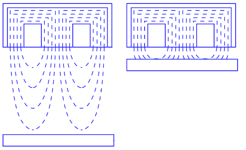
Let us now consider the principle of operation of an inductive sensor. As mentioned above, when the metal is close enough to the trigger zone, the sensor is activated. This phenomenon consists in the interaction of the involved inductors with metal approaching it, which sharply changes the magnitude of the magnetic field of the coil, which leads to the activation of the sensor, it is triggered, the corresponding signal appears at its output.
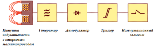
The electronic part of the device contains a control circuit, which in turn controls a relay or transistor switch. It consists of the following parts:
-
A generator that creates an electromagnetic field needed to interact with an object.
-
Schmitt trigger providing switching hysteresis.
-
An amplifier to increase the amplitude of the signal so that it reaches the required actuation value.
-
LED indicator informing about the status of the switch. It also provides performance monitoring and configuration.
-
Compound to protect against penetration of solid particles and water.
-
Housing for mounting the sensor and protection from various mechanical influences. It is made of brass or polyamide and is finished with fasteners.
Inductive position sensors are widely used in industrial automation systems where it is necessary to periodically or constantly determine the position of any part of the mechanism. The sensor generates a signal that is sent to the drive. A starter, controller, relay, frequency converter, etc. can act as an executive mechanism. The main thing is that the parameters of the sensor correspond to the parameters of the drive in terms of voltage and current.
Most of the sensors are not power devices, they are primarily signaling devices, therefore the sensor itself, as a rule, does not switch anything powerful, but only controls, gives a control signal, acts as an action initiation device that can already be connected to power switching .
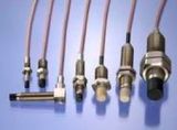
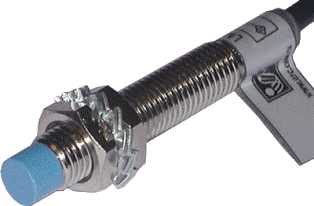
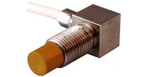
Modern inductive position sensors are most often found in two versions of plastic or metal housings: rectangular or cylindrical. The diameter of the sensor with a circular cross-section can be from 4 to 30 mm, but the most commonly used diameters are 18 and 12 mm.
When the sensor is mounted on equipment, a gap is set between the metal plate and the sensor's actuation zone, usually this distance does not exceed the diameter of the sensor and, as a rule, it turns out to be 2-3 times smaller than its diameter.
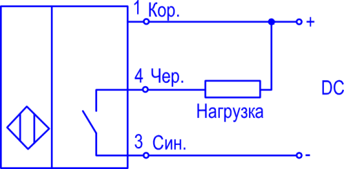
According to the connection method, inductive position sensors can be two-wire, three-wire, four-wire and five-wire.
Two-wire directly switch the load, such as starter coil, that is, they work like a conventional switch. Two-wire sensors require load resistance, so they are not always suitable as a reliable tool, but they do not lose their relevance.
The load is simply connected in series with the sensor, if constant voltage is used then it is important to observe the polarity, if alternating polarity is not important, the main thing is the switched power and current.
Three-wire sensors have a third wire to power the sensor itself, and this is the most popular solution. Four-wire and five-wire sensors have transistor or relay outputs for connecting the load, and the fifth wire allows you to select the operating mode of the sensor, the initial state of the outputs.
Since the outputs can be both relay and transistor, the sensors are accordingly divided into three types according to the device of the outputs: relay, npn and pnp.
Sensors with relay output
A sensor with a relay output has galvanic isolation of the supply circuit from the included circuit. It switches one wire and the voltage in the switched circuit is not particularly critical. Since the power supply circuit of the sensor is galvanically isolated, this can be considered an advantage of the relay sensor. Sensors of this type are usually large.
Sensors with pnp transistor output
The sensor has a pnp transistor at the output which commutates the positive wire with the load. A load is connected to the collector circuit of the output pnp transistor, which is permanently connected to negative through its second lead.
Sensors with npn transistor output
The sensor has an NPN transistor at the output which commutates the negative wire with the load. A load is connected to the collector circuit of the output npn transistor, which is permanently connected by its second lead to the positive lead.
According to the initial state of the outputs, inductive position sensors can be normally closed or normally open contacts. The initial state means that this state is at the moment when the sensor is not yet triggered, that is, it is not activated.
If the output contacts are normally closed, then the load is connected at idle time, if it is normally open, then until the sensor is triggered, the load will be cut off and no power will be supplied to the drive (e.g. contactor). Normally closed contacts are designated in English format — N.C. (Normally Closed), Normally Open — N.O. (Normally open).
Thus, sensors with transistor outputs are of four types: two types according to the conductivity (pnp or npn) and two types according to the initial state of the outputs. There may also be a delay when turning on or off.
Depending on the type of drive that is connected to the sensor, as well as the power supply method, the logic of the sensor can be positive or negative. This is due to the voltage level that activates the input of the device.
If the input is activated when the negative wire of the actuator is connected to the ground, to the minus, then the logic is called negative, such a connection is characteristic of sensors with npn type transistor outputs.
Positive logic corresponds to connecting the drive's positive wire to the positive power supply when activated, this logic is typical of sensors with pnp transistor outputs. Most often, there is a positive logic to the operation of inductive sensors for the position of the mechanisms.
Older most commonly used types of inductive position sensors
Inductive position sensors IKV-22
Inductive sensors IKV-22. The operation of these sensors is based on the principle of changing the inductive resistance of coils with a steel core when the air gap in the magnetic circuit changes.
A magnetic circuit with two coils is mounted on a steel plate, closed with a plastic cover. Two MBGP capacitors (one with a capacity of 15 μF, 200 V, the other with a capacity of 10 μF, 400 V) are attached to the plate from the bottom side. The capacitors are covered with a cover. The cable is connected through the seal. A magnetic shunt is installed on the mechanism, the dimensions of which must be at least: thickness 2 mm, width 80 mm, length 140 mm. The air gap between the magnetic circuit and the shunt is 6 ± 4 mm.
The output relay is usually turned on and off at the moment when the magnetic shunt passes through the sensor, when due to a change in the inductive resistance of the coil, current resonance occurs and the current through the relay coil drops. These relays: type MKU-48, 12 V AC, draw current not more than 0.45 A, drop current not less than 0.1 A.The supply voltage of the sensor circuit is 24 V AC relay.
Inductive position sensors ID-5
In metallurgical workshops, inductive sensors of the ID-5 type are used, designed to work at ambient temperatures up to + 80 ° C and humidity up to 100%. Conductive dust and scale are acceptable. A UID-10 type semiconductor output amplifier is used with the sensor. The output power of the amplifier (25 W) is sufficient to turn on the widespread REV-800 relays, contactors KP21, MK-1, etc.
The air gap between the sensor and the observed ferromagnetic object can be up to 30 mm. The dimensions of the ID-5 sensor are 187x170x70 mm, the supply voltage is 220 V ± 15%, 50 Hz.
Small size BSP contactless switches
Small motion switches BSP-2 (with non-contact output, to logic element) and BRP (with output to relay PE-21, 24 V, 16 Ohm) are used on metal cutting machines.
The BSP-2 switch consists of a differential transformer sensor and a semiconductor trigger. The magnetic system of the first sensor coil is moved by a steel plate, and the second coil is manipulated as it moves over its magnetic system connected to the flat armature mechanism. The coils are turned on in the opposite direction.
If the armature is above the sensor, the inductive reactances of the coils are equal and the sensor output of the differential transformer is zero. In this case, a voltage of at least 2.5 V appears at the output of the trigger, which is enough for the logic element to work.
In the absence of an armature above the sensor, a voltage is applied to the trigger, which returns it to its original state. Then the output signal of the switch is zero.
The principle of operation of the BRP switch is in many ways similar to that of the BSP-2. An inductive sensor (according to the circuit of the differential transformer), a trigger and an amplifier are installed inside the box. Secondary coils with a different number of turns are switched on in the opposite direction. As the armature overlaps the magnetic system of the sensor, the signal decreases and after changing the phase, the trigger is switched and an external output relay (PE-21, 24 V, 16 Ohm) is activated.
The anchor fixed to the mechanism has dimensions of 80x15x3 mm. The gap between the anchor and the sensor is 4 mm. The accuracy of the switches in the nominal mode is ± 0.5 mm, the actuation differential is no more than 5 mm. At. fluctuations in supply voltage and temperature, the error of BSP-2 and BRP switches can reach ± (2.5-f-3.0) mm.
High frequency inductive sensors VKB
High-precision inductive sensors of the VKB type with a U-shaped or flat armature are also used for the automation of metal cutting machines. The poles of the built-in transformer form an open electromagnetic system. The working air gap is 0.1-0.15 mm.
The output voltage from the secondary winding of the transformer is fed to a differential measurement circuit and then to a transistor amplifier. The total error of the sensor with temperature fluctuations from 5 to 40 ° C and voltage from 85 to 110% of the nominal value is ± (0.064-0.15) mm, the difference in response does not exceed 0.4 mm. The maximum movement speed of the mechanism is 10 m / mm. Sensor dimensions 62x34x24 mm. Supply voltage 12 V.
Special types of precision inductive sensors for metal cutting machines with a differential circuit have an error of less than ± 0.01 mm.Such sensors include a non-contact motion switch of the VPB12 type, consisting of a sensor unit on an electronic unit. The sensor unit includes an inductive work sensor, an inductive compensation sensor and printed circuit boards. The mechanism is mounted: control ferrite element. Supply voltage 12 V DC. The maximum exposure distance is no more than 0.12 mm. An RPU-0 type relay can be connected to the sensor output. The maximum load current of the output device is 0.16 A.
Generator position sensors
Sensors of this type are compact and very accurate. Sensor generators of the KVD-6M and KVD-25 series (with slots), KVP-8 and KVP-16 (aircraft) have proven themselves well. They are suitable for use in high concentrations of moisture and dust. The elements of the transistor circuit of the sensor (generator and trigger) are located in a housing made of shock-resistant polystyrene. Sealing is done with a cold-hardening compound. The operating temperature range is from — 30 to +50 ° C.
The HPC sensor generates a discrete signal when a metal plate («flag») passes through the slot, causing a breakdown in the generation and switching of the trigger. The width of the slot is 6 mm for the KVD-6M sensor and 25 mm for the KVD-25 sensor.
The KVP-8 and KVP-16 sensors are activated when a metal plate passes by them at a maximum distance of 8 and 16 mm, respectively.