Brake electromagnets for cranes
 Brake electromagnets designed to control mechanical brakes. In turn, these brakes serve to stop the crane mechanisms in a given position or limit the braking distance in case of leakage with the drive motor turned off.
Shoe and band brakes are most widely used for crane mechanisms (if necessary, have braking moments above 10 kN NS m) — spring and sometimes load. Disc brakes are used less often (braking moment up to 1 kN x m) and conical (braking moment up to 50 N NS m).
The coils of the brake electromagnets turn on simultaneously with the electric motor and release the brake. When the electric motor is turned off, the coils of the brake solenoid are simultaneously de-aired and braking occurs — the brake is tightened under the action of a spring or load.
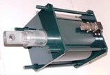
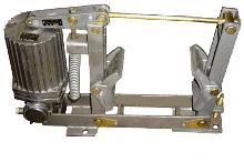
Brake electromagnets with alternating current are used for brakes of crane mechanisms: three-phase KMT series (Fig. 1)-long stroke (maximum armature stroke from 50 to 80 mm), single-phase MO series (Fig.2)-short-stroke (brake rod stroke from 3 to 4 mm), direct current: KMP and VM series — long stroke (armature stroke from 40 to 120 mm), MP series (Fig. 3) — short stroke ( anchor stroke from 3 to 4.5 mm).
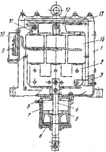
Rice. 1. KMT series brake electromagnet: 1 — housing, 2 — anchor, 3 — guides, 4 — rod, 5 — piston, 6 ~ damper cover, 7 — damper cylinder, 8 — compression adjustment screw, 9 — terminal block , 10 — terminal block cover, 11 — brass coil holders, 12 — yoke, 13 — cover, 14 — coil
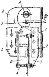
Rice. 2. MO series brake electromagnet: 1 — fixed yoke, 2 — short circuit, 3 — square, 4 — cover, 5 — coil, .6 — armature, 7 — strip, 8 — cheek, 9 — axle, 10 — thrust
The main parameters of brake electromagnets with translationally moving armature (KMT, KMP, VM and MP) are the traction force and armature stroke, and for valve electromagnets of the MO series, the electromagnet moment and armature rotation angle.
The brake solenoids of all the above series are independent electrical appliancesarticulated with brakes.
TS series shoe brakes with short stroke electromagnets and TKP spring brake boats (see Fig. 3) with built-in DC coils. For these brakes, lever 1 is molded together with the solenoid housing and the solenoid armature is cast with the lever.
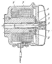
Rice. 3. Brake electromagnet of the MP series: 1 — body, 2 — coil, 3 — armature, 4 — pin, 5 — these otoliths and bushings, 6 — cover, 7 — damping spring, 8 — pole
The coils of the AC brake solenoids are connected in parallel and are designed for the full line voltage. When they are turned on, a significant current shock occurs: for electromagnets of the KMT series Azstart = (10-30) Aznumer, series MO — Azstart = (5-6) AzNo.
When selecting protective devices such as fuses, the inrush current must be considered. The starting current is determined by the formulas
Azstart = Cp / √3U
for three-phase electromagnets
Istart = Sp / U
where, CNS — full power at the time of starting, VA, mains voltage, V.
Brake solenoid coils of DC current can be series and parallel connection (excitation).
 Electromagnets from the series connection coil are fast-acting due to low inductance and reliable in operation as they provide braking, the mechanism for rocks in the armature circuit of the electric motor. Their disadvantage is the possibility of false braking with subsequent disinhibition at very low load, for example at idle. Therefore, it is advisable to use them for crane mechanisms with relatively small fluctuations of the load and therefore the magnitude of the armature current, for example, for crane movement mechanisms.
The current values for the lifting mechanisms are about 40% of the rated current of the electric motor, and for the traveling mechanisms - about 60%. Therefore, the magnitude of the traction force or torque of the coil brakes is consistently indicated in the catalogs for two values of the coil current: for 40 and 60% of the nominal (respectively for lifting and moving mechanisms).
If in the process of starting the electric motor, the minimum value of the current flowing through the coil of the brake electromagnet is less than 40 or 60% of the nominal value, then it is necessary to reduce the braking torque to the values indicated for the current value of 40 or 60% than the nominal (by reducing the brake spring force or brake weight).
 DC brake electromagnets with parallel connection coils do not have the above disadvantages. However, due to the significant inductance of the coils, these electromagnets are inertial. In addition, they are less reliable, since when the armature circuit of the electric motor is broken, the windings of these electromagnets continue to flow around the current, and the brake remains without a brake.
The first drawback can be eliminated by forcing, for which, in series with the coil, an economic resistance is included, which during the retraction of the electromagnetic armature, maneuvers the current relay with the opening contacts and enters the electrical circuit after the electromagnet armature is withdrawn, reducing the current in the coil and its heating accordingly.
The second disadvantage is eliminated by connecting the coil of the current relay in series with the armature of the electric motor and closing it in series with the coil circuit of the electromagnet. When using forcing, the forcing time should be no more than 0.3 — 0.6 s.
To supply electromagnets with direct current from an alternating current network, standard half-wave rectifiers with diodes for a current of up to 3 A and a group of capacitors with a capacity of 2 to 14 μF are used, which provides output parameters that correspond to the conditions for the supply windings of electromagnets.
Alternating current braking electromagnets are widely used for crane installations, but the practice of their work has shown that they have a number of disadvantages: relatively low wear resistance, significant coil switching currents 7 — 30 times higher than their rated currents (with fully retracted armatures), strong shocks during braking and release due to the lack of regulation of the smoothness of the braking process, damage to the coils due to overheating with incomplete retraction of the armature.
 A common drawback of DC and AC brake electromagnets is the imperfection of traction characteristics: at the beginning of the armature stroke, develop the smallest traction force, and at the end - the largest.
With all these disadvantages, DC brake electromagnets are more reliable in operation than AC electromagnets. Therefore, to control the brakes of crane mechanisms with AC power equipment, DC brake electromagnets powered by semiconductor rectifiers are often tried.
Considering that brake electromagnets have a number of significant disadvantages mentioned above, they are currently widely used to drive crane brakes. long-stroke electro-hydraulic thrusters.