Line overcurrent protection
Line overcurrent protection
 Overcurrent protection (overcurrent protection) of lines is widespread in single-feed radial networks and is installed on each line.
The selectivity is achieved by selecting the parameters ICp and tss — protection operation currents and protection operation time.
The selection conditions are as follows:
a) Cut-off current Iss > Azp max i,
where: azp max i is the maximum operating current of the line.
b) reaction time tsz i = tss (i-1) max + Δt,
where: tss (i-1) max is the maximum response time of the protection of the previous line, Δt is the level of selectivity.
The selection of the response time of the overcurrent protection with independent (a) and dependent (b) characteristics is shown in fig. 1 for a radial network.
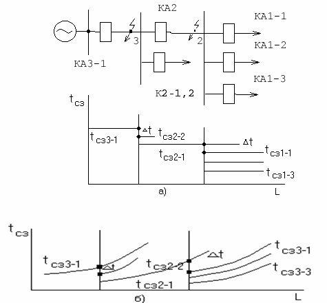
Rice. 1. Selection of response time of overcurrent protection with independent (a) and dependent (b) characteristics.
The operating current of the overcurrent protection is expressed by the formula:
AzSZ = KotKz'Ip max / Kv,
where: K.ot — adjustment coefficient, Kh ' — self-start coefficient, Kv Is the coefficient of return.For relays with direct action: Kot = 1.5 -1.8, Kv = 0.65 — 0.7.
For an indirect relay: Kot = 1.2 — 1.3, Kv = 0.8 — 0.85.
Coefficient of self-start: Kc= 1.5 — 6.
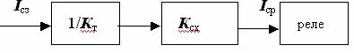
Rice. 2. Block diagram of switching on an indirect-acting relay.
The indirect relay is characterized by switching on the relay itself through a current transformer and a circuit with transmission coefficients KT and K.cx as shown in fig. 2. Therefore, the current in the protected line Iss related to the operating current of the relay ICp according to the formula: ICp = KcxAzCZ/ KT.
ISR = KotKxKscAzp max/ KvKT.
The protection sensitivity coefficient is characterized by the ratio of the current in the relay in short-circuit mode with minimum current (I rk.min) to the operating current of the relay (Iav): K3 = IPK. MIN / AzSr > 1.
MTZ is considered sensitive if K3 with a short circuit of the protected line at least 1.5-2 and with a short circuit (short circuit) in the previous section, where this protection works as a backup, at least 1.2. This means that P3 should have K3 = 1.5 -2, with a short circuit in T.3 and K3 = 1.2 with a short circuit in T.2. (Fig. 1).
Conclusions:
a) the selectivity of the MTZ is provided only in a radial network with one power source,
b) the protection is not fast-acting and the longest delay in the head sections where fast short-circuiting is particularly important,
c) the protection is simple and reliable, applied to current relay RT-40 series and time relay and RT-80 relay for independent and current dependent response characteristics respectively,
d) used in radial networks <35kV.
Current line break
Overload is a fast-acting protection.The selectivity is ensured by the selection of the operating current, which is greater than the maximum short-circuit current in the event of a short circuit in the network points of the unprotected area.
Izz = Cot• Azdo out max,
where: K.ot — setting factor (1.2 — 1.3), Ida ext. Max - maximum short-circuit current for an out-of-zone short circuit.
Hence the overcurrent protects part of the line as shown in fig. 3 for the case of a three-phase short circuit
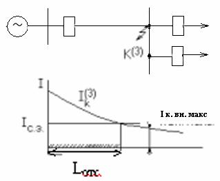
Rice. 3. Protection of part of the line by interruption of current.
Breaking current of the relay: IСр = KcxАзС.З./KT
However, for a dead-end substation, it is possible to fully protect the line before entering the transformer by setting a low-side short-circuit current protection as shown in Fig. 4 for the case of short circuit in T.2.
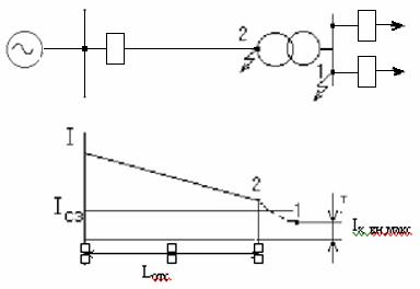
Figure 4. Dead-end substation protection scheme.
Conclusions:
a) the selectivity of the current interruption is ensured by the selection of the operating current greater than the maximum current of the external short circuit and is carried out in networks of any configuration with any number of power sources,
b) fast-acting protection, working reliably in the sections of the head where fast shutdown is required,
c) mainly defends part of the line, has a defensive zone and therefore cannot be the main defence.
Linear differential protection
Longitudinal differential protection reacts to changes in the difference between currents or their phases, comparing their values with the help of measuring devices installed at the beginning and end of the line. For longitudinal protection, comparing the currents shown in Fig. 5, the operating current of the relay. AzCr is defined by the expression: ICr1c - i2c.
Rice. 5… Protection circuit with longitudinal differential line.
In normal line mode or external mode K3(K1), in the primary windings of current transformers, in both cases the same currents flow, and in the relay the difference of the currents: IR = Az1v — Az2v
In the case of internal K3 (K2), the relay current becomes: IR= Az1v+ Az2v
With unidirectional power supply and internal K3 (K2) I2c= 0 and relay current: IR= Az1c
With external K3, the imbalance current I passes through the relay caused by the difference in the characteristics of the TP:
AzR = Aznb = Az1c — Az2c= Az '2 us — Az '1 us,
where I1, I2 are TA magnetizing currents reduced to the primary windings.
The unbalance current increases with increasing primary current K3 and in transient modes.
The operating current of the relay must be regulated by the maximum value of the unbalance current: IRotsinb max
The protective sensitivity is defined as: K3 = Azdo min/ KT3Sr
Even for relatively short transmission lines of commercial networks of industrial enterprises, TPs are located far from each other. Since the protection must open both switches Q1 and Q2, two TAs are installed at the ends of the line, which leads to an increase in the unbalance current and a decrease in the current in the relay at K3 of the line, since the secondary winding current is distributed over 2 TA.
To increase the sensitivity and adjust the differential protection, special differential relays with a stop are used, the relay is turned on by an intermediate saturated TA (NTT) and automatic deactivation of the protection.
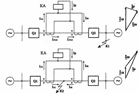
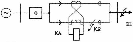
Lateral protection is based on comparing the currents of the same phases at one end of parallel lines. For lateral protection of parallel lines shown in fig. 6, relay current IR = Az1v - Az2v.
Rice. 6… Parallel line cross protection circuit
With external K3 (K1), the relay has an unbalance current: IR = Aznb.
The operating current of the relay is determined similarly to the longitudinal protection.
At K3 (K2), the protection is triggered, but if K2 moves to the end of the line, due to the fact that the difference in currents decreases, the protection does not work. In addition, cross protection does not reveal a damaged cable, which means that it cannot be the main protection of parallel lines.
The introduction of a double-acting power steering element in the circuit eliminates this drawback. With K3 on one of the lines, the power direction relays allow the circuit breaker on the faulted line to be operated.
Longitudinal and lateral differential protection are widely used in power supply systems to protect transformers, generators, cable parallel lines in combination with overcurrent protection.