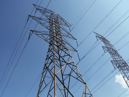
Earthing systems for electrical networks up to and above 1000 V
There are several options for the operation of electrical networks, depending on their grounding system. Let us briefly characterize the existing grounding systems for electrical networks with a voltage class up to and above 1000 V.
Networks with voltage class up to 1000 V
TN-C system
In the electrical network of this configuration, the neutral terminal of the supply transformer is firmly grounded, that is, it is electrically connected to the earth loop of the transformer substation. Along the entire length from the substation to the consumer, the neutral and protective conductors are united in one common - so-called. PEN wire.
This network provides "Neutralization" of electrical appliances — connecting the neutral and protective conductors to the combined PEN conductor. This network is obsolete and only applied in industry and street lighting.
The resetting of electrical appliances in everyday life is prohibited due to the danger of creating a dangerous potential on the reset buildings, which is why such a network in old buildings is operated exclusively as two-wire — only neutral and phase wires are used.
TN-C-S system
This network differs from the previous one in that the combined PEN wire is divided at a certain point, as a rule, after entering the building — into a neutral wire N and a protective grounding wire PE.
The TN-C-S configuration network is the most common in our time. This network is one of the recommended systems according to PUE and can be implemented in new facilities.
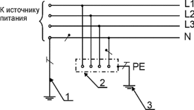
Grounding system TN-C:
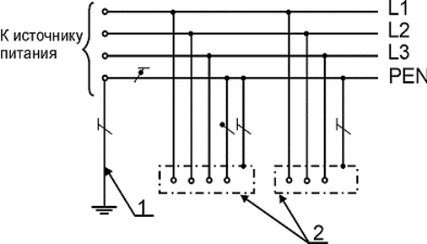
1 — ground wire of the zero (middle point) of the power supply, 2 — exposed conductive parts, N — neutral working wire — neutral working (neutral) wire, PE — protective wire — protective wire (grounding wire, zero protective wire, protective wire of the equipotential bonding system), PEN — combined neutral protective and neutral working conductors — combined neutral protective and neutral working conductors.
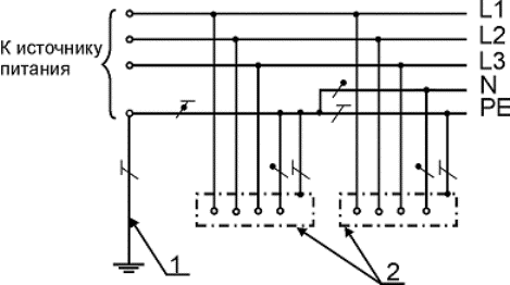
TN-S system
The configuration of this electrical network differs from the previous ones in that it provides for the separation of the combined conductor of the power substation, along the entire length of the line, the neutral and ground conductors are separated.
This system is used in the construction of new facilities and is the most preferred of all available. But due to the higher cost of implementation (the need to place a separate protective conductor), the TN-C-S configuration network is often preferred.
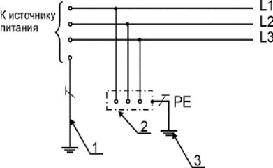
TN-S grounding system:
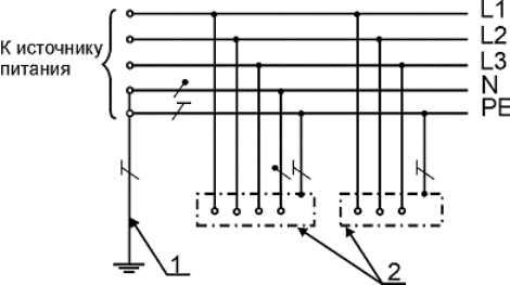
Grounding system TN-C-S:
TT system
Then power transformer neutral also has a hard ground, but the end user's wiring is grounded by a separate ground loop that is not electrically connected to the grounded neutral of the transformer.
This earthing system is recommended for use in the event of an unsatisfactory condition of the electrical networks, where the operation of the provided earthing may be dangerous.
Basically, these are TN-C networks, in which grounding is not provided in principle, as well as TN-CS networks, which do not meet the requirements of the PUE in terms of the mechanical strength of the combined conductor, as well as the presence of its multiple grounding.
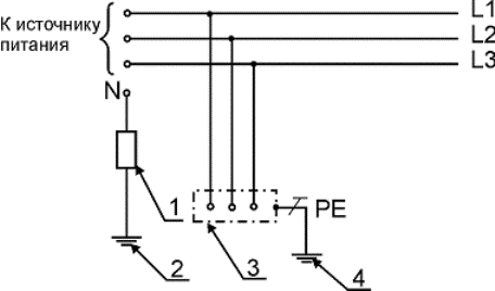
TT grounding system:
1 — grounding conductor of the zero (middle point) of the power supply, 2 — exposed conductive parts, 3 — grounding conductor of exposed conductive parts, N — neutral working conductor — neutral working (zero) conductor, PE — protective conductor — protective conductor (grounding conductor , neutral protective conductor, protective conductor of the equipotential bonding system).
Information System
The neutrals of the power transformers in the network of this configuration are not grounded, that is, they are isolated from the ground circuit of the substation. The protective earth conductor can be connected to the substation earth loop or directly at the user to the existing earth loop.
IT grounding system:
1 — grounding resistance of the zero of the power supply (if any), 2 — grounding wire, 3 — exposed conductive parts, 4 — grounding device, PE — protective conductor — protective conductor (grounding conductor, neutral protective conductor, protective conductor of the equipotential bonding).
This grounding system is used to power equipment that has special safety and reliability requirements. These are the premises of electrical installations of power plants, substations, hazardous industries, in particular the mining industry, blasting rooms, etc.
Networks with a voltage class above 1000 V
Electrical installations and networks of voltage class 6, 10 and 35 kV work in most cases in isolated neutral mode… Due to the lack of neutral grounding, a short circuit of one of the phases to ground is not a short circuit and is not disabled by the protection.
In the event of a short circuit in the network of this configuration, its short-term operation is allowed, as a rule, for the time to find the damaged section and disconnect it from the network. That is, in the presence of a short circuit in the network with an isolated neutral, consumers do not lose power, but continue to work in the same mode, with the exception of the damaged zone, in which an incomplete phase mode is observed - a break in one of the phases.
The danger of this network lies in the fact that in the event of a single-phase short circuit, the currents spread to the ground from the point where the conductor falls 8 m in open space and 4 m indoors. A person who falls within the range of propagation of these currents will be fatally shocked.
The neutral network of 6 and 10 kV can be grounded special compensating reactors and arc suppression coils to compensate for ground fault currents. This system of grounding networks is used in the presence of large earth fault currents, which can be dangerous for the electrical equipment of these networks.Such a grounding system for electrical networks is called resonant or compensated.
Power networks with voltage class 110 and 150 kV have an effective earthing system. With this grounding system, most power transformers in the electrical network have a solid neutral grounding and some transformers have a neutral grounding through arresters or surge arresters... Selective grounding of the neutrals reduces short circuit currents in electrical networks.
As a result of calculations, it is chosen at which substations the neutrals of the transformers will be grounded in order to ensure the most efficient operation of the electrical network. The grounding of the neutrals through arresters or surge arresters is carried out in order to protect the winding of the power transformers from possible overvoltage.
Networks with a voltage class of 220-750 kV operate in solidly grounded neutral mode, that is, in such networks, all outputs of the neutral windings of power transformers and autotransformers are electrically connected to substation ground loop.