Capacitive compensation
Reactive power compensation achieved with an additional capacitive load is called capacitive compensation. This type of compensation is traditional for AC traction substations in the Russian Federation, where in this way it is possible to significantly increase the efficiency of equipment and reduce losses.
For example, the throughput of railway electric transport is greatly increased due to capacitive compensation of reactive power, that is, through the use of capacitor blocks. And as the mains voltage changes in one way or another, then the capacitor banks must be adjusted. Capacitive compensation can be longitudinal, transverse and longitudinal-transverse, which will be described in detail later in the text.
Side Capacitive Compensation — KU
Capacitive side compensation refers to the reduction of the reactive current component due to the connection of an additional reactive power source directly to the load. Custom capacitor banks include not only capacitors but also reactorsconnected in series or parallel with capacitors. Step devices allow switching off and on individual steps of the capacitor or even changing the connection scheme of the device.
Regulated condensing units with reactors
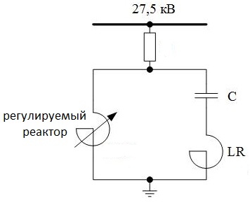
If a controlled reactor is connected in parallel to the capacitor bank, then the total reactive power of such a capacitor plant will be equal to the difference between the reactive powers of the reactor and the capacitance. In particular, if the reactive power of the capacitor bank is equal to the reactive power of the reactor, then the plant as a whole will generate no reactive power at all.
By adjusting the parameters of the reactor, reducing its power accordingly, the reactive power generated by the entire capacitor bank is increased. The state of the reactor is regulated by adjusting the saturation of the steel of the magnetic circuit when it is transversely or longitudinally magnetized by direct current. Today, transverse deflection of reactors is no longer used due to the uneconomical nature of this approach.
Today, almost everywhere in networks, starting from 35 kV, reactors are regulated thyristors… The magnitude of the reactor current from zero to nominal is set in such circuits through the firing angle of the thyristors. This method of controlling the reactors is quite reliable, although it involves with the presence of higher harmonics, which must be eliminated by filters with odd harmonics.
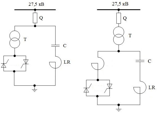
To reduce the voltage with which the thyristors operate here, a reactor-transformer is used or a capacitor bank and a circuit with thyristors are connected through a step-down transformer (autotransformer).
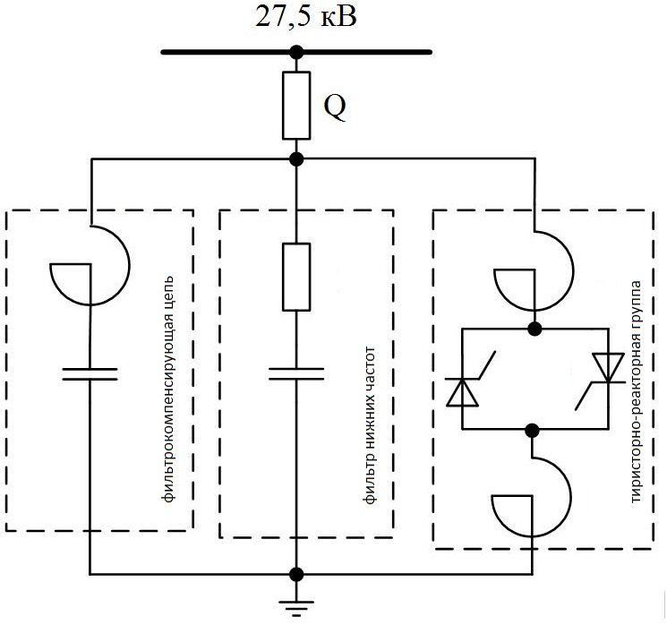
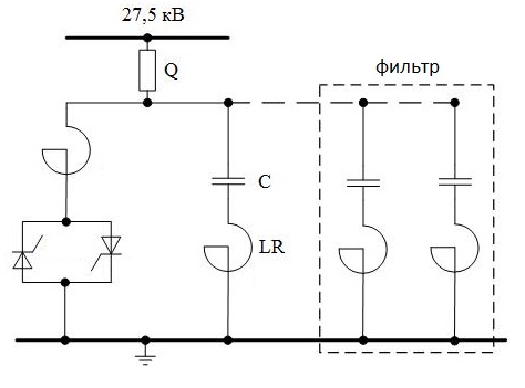
The figure shows a diagram of a static thyristor compensator with a group of reactors, which is controlled by thyristors and has filtering compensator circuits. In general, the compensator includes:
-
single-phase thyristor-reactor group, which allows smooth regulation of reactive power;
-
a filter-compensating circuit that serves as a filter with higher harmonics and a source of reactive power;
-
A low-pass filter that reduces the destructive effect of resonance phenomena for the thyristor compensator.
In addition, the static compensator includes a control and protection system consisting of thyristor blocks for control and relay protection, as well as a thyristor cooling module.
Units with step regulation
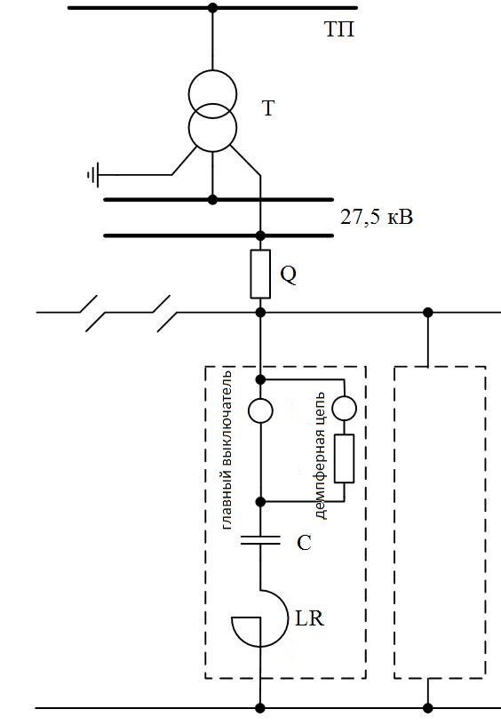
A step regulation installation includes several sections, so that, if necessary, to adjust the current, voltage or reactive power, it would be possible to disconnect or connect one or the other section. The installation contains a capacitor bank, a reactor, an extinguishing circuit and a main switch.
The most important thing in the design of a capacitor module with step regulation is to correctly organize the limitation of overvoltages and currents at the moments of connection and disconnection of sections. Transient processes are a factor in the reduced reliability of such installations.
Longitudinal capacitive compensation — UPC
To reduce the influence of the inductive component of the traction network and the transformer on the voltage of the pantographs of electric locomotives, longitudinal capacitive compensation installations are used, that is, capacitors are connected in series with them.
At traction substations in Russia, longitudinal compensation installations are placed in suction lines, where these installations increase the voltage, help eliminate the effects of phase advance or lag, promote voltage symmetry at equal currents in the arms, lower the voltage class of the equipment and generally simplify the installation design.
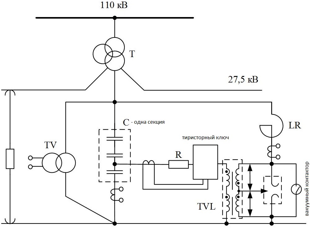
The figure shows one of these sections. Here, through capacitors and a resistor, through a thyristor switch, the voltage is supplied to the low-voltage windings of two transformers connected in series. The high voltage windings of these transformers are connected in opposite directions. At the moment of short circuit, the voltage on the capacitors of the installation increases. And as soon as the voltage reaches the setting level, the thyristor switch opens, the arc immediately ignites in the discharger and continues to burn until the vacuum contactor closes for a fraction of a second.
Such settings help to reduce voltage fluctuations in pantographs and make bus voltages symmetrical. Disadvantages include the more difficult operating conditions of capacitors, in connection with which installations of this type require ultrafast protection. It is best to use CPC together with KU.