Methods and means of voltage regulation of electrical receivers
In order to provide some predetermined values of voltage deviations for electrical receivers, the following methods are used:
1. Regulation of the voltage in the buses of the energy center;
2. Change in the amount of voltage loss in network elements;
3. Change in the value of the transmitted reactive power.
4. Changing the transformation ratio of transformers.
Voltage regulation on power center busbars
Voltage regulation in the power supply center (CPU) leads to voltage changes in the entire network connected to the CPU and is called centralized, the rest of the regulation methods change the voltage in a certain area and are called local voltage regulation methods. As a processor of city networks it can be considered buses for the generator voltage of the thermal power station or low voltage busbars of district substations or deep insertion substations. Therefore, voltage regulation methods follow.
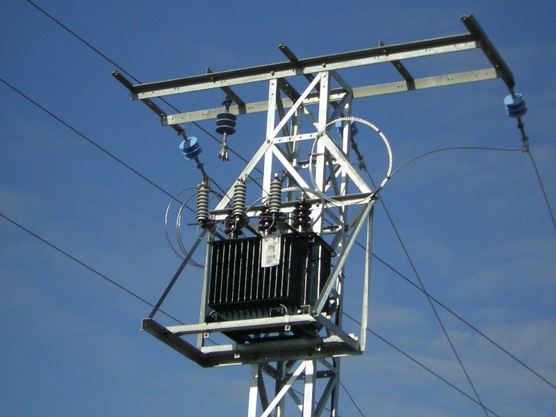
At the generator voltage, it is produced automatically by changing the excitation current of the generators. Deviations from the nominal voltage within ± 5% are allowed. On the low-voltage side of regional substations, regulation is done using load-controlled transformers (OLTCs), linear regulators (LRs) and synchronous compensators (SKs).
For different customer requirements, the control devices can be used together. Such systems are called centralized group voltage regulation.
As a rule, counter-regulation is carried out on the processor buses, that is, such regulation in which during the hours of the greatest loads, when the voltage losses in the network are also the greatest, the voltage rises, and during the hour of minimum loads, it decreases.
Transformers with load switches allow a fairly large range of control up to ± 10-12%, and in some cases (transformers of the TDN type with a higher voltage of 110 kV up to 16% on 9 stages of regulation There are projects for modulating control on load , but they are still expensive and are used in exceptional cases with particularly high requirements.
Change in the degree of voltage loss in network elements
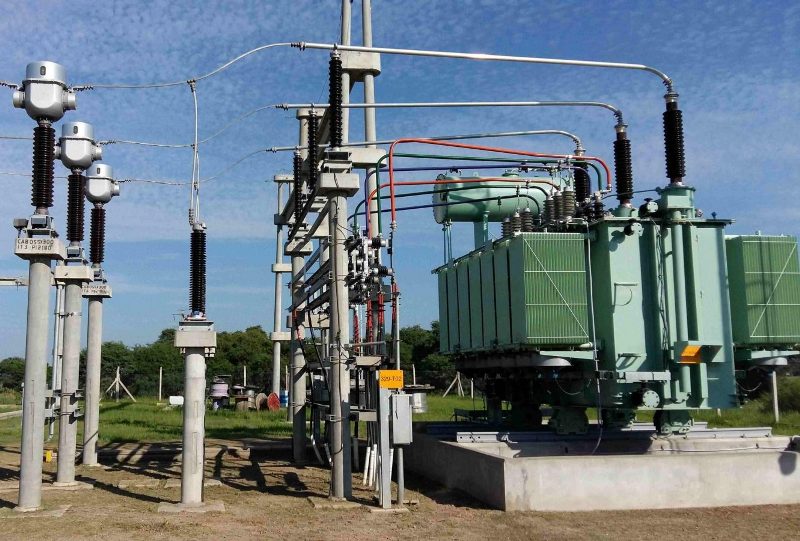
Changing the voltage loss in the network elements can be done by changing the resistance of the circuit, for example, changing the cross-section of wires and cables, turning off or turning on the number of parallel connected lines and transformers (see- Parallel operation of transformers).
The choice of cross-sections of wires, as is known, is made on the basis of heating conditions, economic current density and permissible voltage loss, as well as mechanical strength conditions. The calculation of the network, especially the high voltage, based on the allowable voltage loss, does not always provide normalized voltage deviations for the electrical receivers. that's why in PUE losses are not normalized, but voltage deviations.
The network resistance can be changed by connecting capacitors in series (longitudinal capacitive compensation).
Longitudinal capacitive compensation is called a method of voltage regulation in which static capacitors are connected in series in the section of each phase of the line to produce voltage spikes.
It is known that the total reactance of an electrical circuit is determined by the difference between inductive and capacitive resistance.
By changing the value of the capacitance of the included capacitors and, accordingly, the value of the capacitive resistance, it is possible to obtain different values of the voltage loss in the line, which is equivalent to the corresponding voltage increase at the terminals of the electrical receivers.
Series connection of capacitors to the network is recommended for low power factors in overhead networks where the voltage loss is mainly determined by its reactive component.
Longitudinal compensation is particularly effective in networks with sharp load fluctuations, as its action is fully automatic and depends on the magnitude of the current flowing.
It should also be taken into account that longitudinal capacitive compensation leads to an increase in short-circuit currents in the network and can cause resonant overvoltages, which requires a special check.
For the purpose of longitudinal compensation, it is not necessary to install capacitors rated for the full operating voltage of the network, but they must be reliably isolated from earth.
See also on this topic: Longitudinal compensation — physical meaning and technical implementation
Change in the value of transmitted reactive power
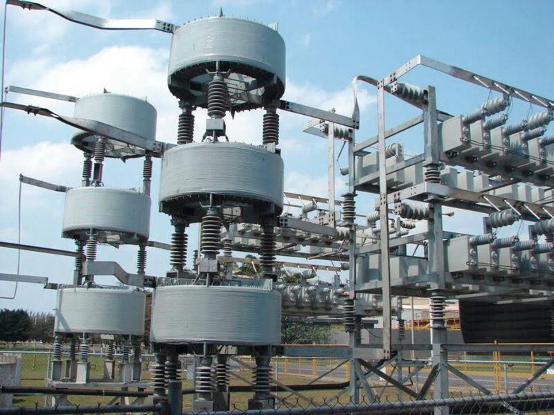
Reactive power can be generated not only by generators of power plants, but also by synchronous compensators and overexcited synchronous electric motors, as well as by static capacitors connected in parallel to the network (transverse compensation).
The power of the compensating devices to be installed in the network is determined by the reactive power balance in a given node of the power system based on technical and economic calculations.
Synchronous motors and capacitor banks, being reactive power sources, can have a significant impact on the voltage regime in the electrical network. In this case, the automatic regulation of the voltage and network of synchronous motors can be carried out without any problems.
As sources of reactive power in large regional substations, special synchronous motors of light construction, which operate in idle mode, are often used. Such engines are called synchronous compensators.
The most widespread and the industry has a series of electric motors SK, produced for a nominal voltage of 380 — 660 V, designed for normal operation with a leading power factor equal to 0.8.
Powerful synchronous compensators are usually installed in regional substations, and synchronous motors are more often used for various drives in industry (powerful pumps, compressors).
The presence of relatively large energy losses in synchronous motors makes it difficult to use them in networks with small loads. Calculations show that in this case static capacitor banks are more suitable. In principle, the effect of shunt compensation capacitors on network voltage levels is similar to the effect of overexcited synchronous motors.
More details about capacitors are described in the article. Static capacitors for reactive power compensationwhere they are considered in terms of power factor improvement.
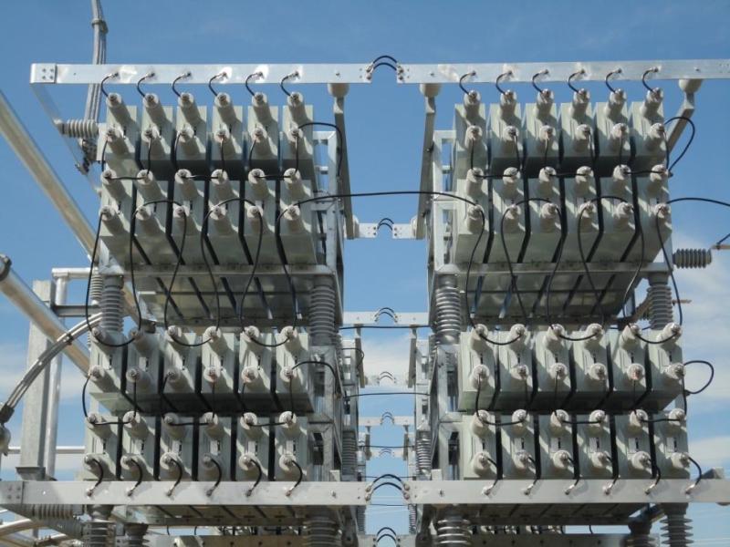
There are a number of schemes for the automation of compensating batteries. These devices are commercially available complete with capacitors. One such diagram is shown here: Capacitor bank wiring diagrams
Changing the transformation ratios of transformers
Currently, power transformers with voltages up to 35 kV are produced for installation in distribution networks turns off the switch for switching control taps in the primary winding. Usually there are 4 such branches, in addition to the main one, which makes it possible to obtain five transformation ratios (voltage steps from 0 to + 10%, on the main branch — + 5%).
Rearranging the taps is the cheapest way of regulation, but it requires disconnecting the transformer from the network and this causes an interruption, albeit short-term, in the power supply of consumers, therefore it is used only for seasonal voltage regulation, i.e. 1-2 times a year before the summer and winter seasons.
There are several computational and graphical methods for selecting the most advantageous transformation ratio.
Let us consider here only one of the simplest and most illustrative. The calculation procedure is as follows:
1. According to PUE, permissible voltage deviations are taken for a given user (or group of users).
2. Bring all the resistances of the considered section of the circuit to one (more often to a high) voltage.
3. Knowing the voltage at the beginning of the high-voltage network, subtract from it the total reduced voltage loss to the consumer for the required load modes.
Power transformers equipped with on-load voltage regulator (OLTC)… Their advantage lies in the fact that regulation is carried out without disconnecting the transformer from the network. There are a large number of circuits with and without automatic control.
The transition from one stage to another is carried out by remote control using an electric drive without interruption of the operating current in the high voltage winding circuit. This is achieved by short-circuiting the regulated current limiting section (choke).
Automatic regulators are very convenient and allow up to 30 switching per day.Regulators are set in such a way that they have a so-called dead zone, which should be 20 - 40% larger than the control step. At the same time, they should not react to short-term voltage changes caused by remote short circuits, starting large electric motors, etc.
It is recommended that the substation scheme be built so that consumers with homogeneous load curves and approximately the same voltage quality requirements.