Overcurrent protection of transformers
 Power transformers are structurally reliable enough due to the absence of rotating parts. During operation, however, damage and disruptions to normal operation are possible and occur. Failure of power transformers: rotation of circuits, short circuit of the case, short circuit of windings, short circuit of inputs, etc., abnormal modes: inadmissible overloads, lowering of the oil level, its decomposition when overheating, passing of an external short compound currents.
Power transformers of relatively low power are usually protected by fuses on the high voltage side and fuses or circuit breakers on the side of the low voltage output lines. The fuse current of the high-voltage fuse is selected taking into account the setting from the magnetizing current surges when the power transformer is turned on under the operating voltage. With this in mind, the rated current of the fuse
where Azhs-current of the high-voltage fuse, A, Azn.tr. — rated current of the transformer, A.
The correspondence of high-voltage fuses to the power transformers protected by them with a voltage of 6 — 10 kV is given in the reference books. Protection by means of fuses is carried out structurally in the simplest way, but there are disadvantages - instability of the protection parameters, which can lead to an unacceptable increase in the protection response time for some types of internal damage of power transformers. With fuse protection, difficulties arise in coordinating the protection of adjacent network sections. More advanced relay overcurrent current protection of transformers (Fig. 1).
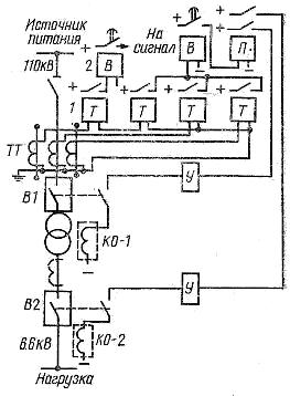
Fig. 1. The scheme of overcurrent current protection against overloading of a step-down two-winding transformer with a direct supply
Current transformers CTs are powered from the high voltage (power) side. If they were installed on the low voltage side (as shown in the diagram with a dotted line), then the protection will only work in the event of faults in the 6.6 kV busbars and the associated loads, since in this case there is a short circuit currents will not to pass through the current transformers...
If any of the three phases of the transformer is damaged, the short-circuit current will pass through the corresponding current transformer, close the contacts of the operating relay T, which will actuate the time relay B, and through it the intermediate relay P, the operating current will activate the tripping coil KO-1 which will trip breaker B1 by disconnecting the protection transformer.
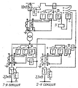
Rice. 2. Scheme of overcurrent current protection of the transformer
In fig. 2 shows a diagram of a transformer substation that supplies two groups of loads on the low voltage side.Here the transformer is protected on both sides with higher and lower voltage. Both sections are powered by separate switches. For normal operation, the circuit provides three sets of overcurrent protection: two of them on the lower voltage side and one on the higher voltage side.
The operating current of the protection installed on the low voltage side is selected according to the load of its circuit, taking into account the starting currents of the motors served by this part of the circuit. The delay is selected according to the conditions of selectivity with protection of the elements connected to this part of the circuit. The operating current of the protection installed on the high voltage side is determined by the total load of the two sections, taking into account the starting currents of the electric motors, and the shutter speed is one step higher than the low voltage side shutter speed.
For overcurrent protection of three winding transformers, one set of protective devices is not sufficient. To disconnect only one winding in the event of a single-voltage system failure and keep the transformer operating with two other windings, it is necessary to supply each winding of the transformer with an independent set of overcurrent protection... The operating current is selected according to the load on each winding . The delay is set according to the selectivity condition with the protection of other elements in the network with a given voltage.
Power transformers usually allow significant overloads. Thus, a transformer of normal design allows double overload in 10 minutes. This time is quite enough for the personnel on duty to unload the transformer.Therefore, overload protection is installed on transformers with a capacity of 560 kVA and above. In substations with permanent personnel on duty, the protection operates on the signal, and in substations without permanent personnel on duty, the protection switches off the overloaded transformer or part of its load.
Instantaneous overcurrent protection with a limited area of operation is called overcurrent... To ensure selectivity in the coverage area, the current interruption is set by the short-circuit currents on the low-voltage side of the transformer, by the starting currents of the electric motors, by the short-circuit current (SC) at the end of the line or at the beginning of the next section. The nature of the change in short-circuit current when the short-circuit point is removed from the power source is shown in Fig.
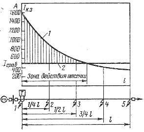
Rice. 3. Diagram of current protection
The operating breaking current is selected in such a way that it does not trip in the event of faults on the adjacent line. For this, the operating current must be greater than the maximum short-circuit current of the low-voltage busbars.
The coverage area is defined graphically as shown in Figure 3. The currents flowing during the short circuit at the beginning (point 1) and at the end of the line (point 5) as well as at points 2 — 4 are calculated. Depending a short-circuit current change curve from the power supply is drawn from the distance (curve 1). The tripping current is determined and tripping current line 2 is drawn on the same graph. The point of intersection of curve 1 with line 2 defines the end of the tripping zone (shaded part).
The interrupting current can protect an entire line to which only one transformer is connected, if the interrupting operating current is chosen so that it does not operate in the event of a low-voltage fault coming out of the transformer to be protected. To do this, the calculation must take into account the maximum short-circuit current observed on the low-voltage buses. In this case, the current interruption will reliably protect the line, busbars and part of the high voltage winding of the transformer.
Trip schemes differ from overcurrent protection schemes in the absence of time relays, instead of which intermediate relays are installed. Overload protection protects only part of the line, so it is used as additional protection. The use of current interruption makes it possible to accelerate the tripping of faults accompanied by the highest values of short-circuit currents and to reduce the time delay of the overcurrent protection. When current interruption is combined with overcurrent protection, time-step current protection is obtained: the first stage (interruption) operates immediately, and the subsequent ones with a time delay.