Earthing calculation — method and formulas for calculating protective earthing of electrical equipment
 Calculation of zero is intended to determine the conditions under which it reliably performs its assigned tasks - quickly disconnects the damaged installation from the network and at the same time ensures the safety of a person touching the zeroed case during an emergency period. According to this protective earthing rely on the breaking capacity as well as the touch safety of the case when the phase is short to ground (calculation of neutral earthing) and of the case (calculation of re-earthing of the neutral protective conductor).
a) Interruption calculation
When one phase is closed to the neutral case, the electrical installation will automatically disconnect if the value of the single-phase short-circuit current (ie between the phase and neutral protective conductor) AND K, A, satisfies the condition

where k — factor of multiplication of the rated current Azn A, the fuse or the current setting of the breaker, A. (The rated current of the fuse is the current, the value of which is indicated (stamped) directly on the insert by the manufacturer.heating above the temperature set by the manufacturer)
A coefficient of value k is accepted depending on the type of protection of the electrical installation. If the protection is carried out by a circuit breaker that has only an electromagnetic release (interruption), that is, triggered without a time delay, then k accepted in the range 1.25-1.4.
If the installation is protected by fuses, the burning time of which depends, as is known, on the current (decreases with increasing current), then in order to speed up the shutdown, take

If the installation is protected by a circuit breaker with an inverse current-dependent characteristic similar to that of fuses, then also
Meaning AND K depends on the phase voltage of the network Uf and circuit resistances, including the impedances of the transformer zt, phase wire zf, neutral protective conductorzns, external inductive resistance of the phase conductor of the loop (loop) — zero protective conductor (phase -zero loops) хn, as well as from the active resistances of the neutral grounding of the windings of the current source (transformer) ro and re-grounding of the neutral protective conductor rn (Fig. 1, a).
Inasmuch as ro and rn are, as a rule, large in comparison with other circuit resistances, it is possible to ignore the parallel branch formed by them. Then the calculation scheme will be simplified (Fig. 1, b), and the expression for the short-circuit current AND K, A, in complex form will be
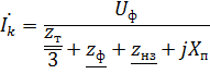
or

where Uf is the phase voltage of the network, V;
zt — complex of impedance of the windings of a three-phase current source (transformer), Ohm;
zf — the impedance complex of the phase conductor, Ohm;
znz — complex of impedance of zero protective conductor, Ohm;
Rf and Rns active resistance of phase and neutral protective conductors, Ohm;
Xf and Xnz — internal inductive resistances of phase and neutral protective conductors, Ohm;
— complex phase of loop impedance — zero, Ohm.
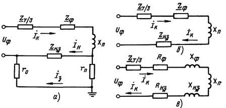
Rice. 1. Calculated scheme of neutralization in the alternating current network for capacity interruption: a — full, b, c — simplified
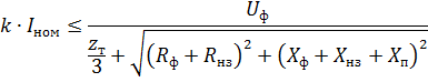
When calculating the reset, it is permissible to use an approximate formula for calculating the actual value (module) of the short-circuit current A, in which the modules of the resistance of the transformer and the phase of the loop are zero zt and zn Ohm, add arithmetically:

Some inaccuracies (about 5%) of this formula strengthen the safety requirements and are therefore considered acceptable.
Loop impedance phase — zero in real form (module) is, Ohm,
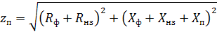
Calculation formula looks like this:
Here, only the resistances of the neutral protective conductor and are unknown, which can be determined by suitable calculations using the same formula. However, these calculations are usually not carried out, because the cross-section of the neutral protective conductor and its material are taken in advance from the condition that the permeability of the neutral protective conductor is at least 50% of the permittivity of the phase conductor, i.e.

or

This condition is established by PUE under the assumption that for such a conductivity Azk will have the required value

It is recommended to use non-insulated or insulated wires such as zero PUE protective wires, as well as various metal structures of buildings, crane tracks, steel pipes for electrical wiring, pipelines, etc.It is recommended to simultaneously use neutral working conductors and as protective neutral conductors. In this case, the neutral working wires must have sufficient conductivity (at least 50% of the conductivity of the phase wire) and must not have fuses and switches.
Therefore, the calculation of resetting the breaking capacity is a check of the calculation of the correctness of the selection of the conductivity of the neutral protective conductor, or rather of the sufficiency of the conductivity of the loop, the phase is zero.
Meaning zT, Ohm, depends on the power of the transformer, the voltage and connection scheme of its windings, as well as on the design of the transformer. When calculating reset, the zm value is taken from tables (for example, table 1).
The values Rf and Rnz, Ohm, for conductors of non-ferrous metals (copper, aluminum) are determined according to known data: cross-section c, mm2, length l, m, and the material of the conductors ρ... In this case, the required resistance

where ρ- the specific resistance of the conductor, equal to 0.018 for copper and 0.028 Ohmm2 / m for aluminum.
Table 1. Approximate values of calculated impedances zt, Ohm, windings of oil-filled three-phase transformers
Transformer power, kV A Rated voltage of high-voltage windings, kV zt, Ohm, with winding connection diagram Y / Yн D / Un U / ZN 25 6-10 3.110 0.906 40 6-10 1.949 0.562 63 6-10 1.237 0.360
20-35 1,136 0,407 100 6-10 0,799 0,226
20-35 0,764 0,327 160 6-10 0,487 0,141
20-35 0,478 0,203 250 6-10 0,312 0,090
20-35 0,305 0,130 400 6-10 0,195 0,056
20-35 0,191 — 630 6-10 0,129 0,042
20-35 0,121 — 1000 6-10 0,081 0.027
20-35 0,077 0,032 1600 6-10 0,054 0,017
20-35 0,051 0,020
Note. These tables refer to transformers with windings of low voltage 400/230 V. At lower voltage 230/127 V, the resistance values given in the table must be reduced by 3 times.
If the neutral protective conductor is steel, then its active resistance is determined using tables, for example, a table. 2, which shows the resistance values of 1 km (rω, Ohm / km) of different steel wires at different current densities with a frequency of 50 Hz.
To do this, you need to set the profile and cross-section of the wire, as well as know its length and the expected value of the short-circuit current I K that will pass through this wire during the emergency period. The cross-section of the wire is adjusted so that the short-circuit current density in it is approximately 0.5-2.0 A / mm2.
Table 2. Active rω and internal inductive xω resistances of steel wires at alternating current (50 Hz), Ohm / km
Dimensions or diameter of the section, mm Section, mm2 rω хω rω хω rω хω rω хω at the expected current density in the conductor, A / mm2 0.5 1.0 1.5 2.0 Rectangular strip 20 x 4 80 5.24 3.14 4.20 2.52 3.48 2.09 2.97 1.78 30 x 4 120 3.66 2.20 2.91 1.75 2.38 1.43 2.04 1.22 30 x 5 150 3.38 2.03 2.56 1.54 2.08 1.25 — — 40 x 4 160 2.80 1.68 2.24 1.34 1.81 1.09 1.54 0, 92 50 x 4 200 2.28 1.37 1.79 1.07 1.45 0.87 1.24 0.74 50 x 5 250 2.10 1.26 1.60 0.96 1.28 0, 77 — — 60 x 5 300 1.77 1.06 1.34 0.8 1.08 0.65 — — Round wire 5 19.63 17.0 10.2 14.4 8.65 12.4 7, 45 10.7 6.4 6 28.27 13.7 8.20 11.2 6.70 9.4 5.65 8.0 4.8 8 50.27 9.60 5.75 7.5 4, 50 6.4 3.84 5.3 3.2 10 78.54 7.20 4.32 5.4 3.24 4.2 2.52 — — 12 113.1 5.60 3.36 4.0 2.40 — — — — 14 150.9 4.55 2.73 3.2 1.92 — — — — 16 201.1 3.72 2.23 2.7 1.60 — — — —
Xph values and Khnz for copper and aluminum conductors are relatively small (about 0.0156 Ohm / km), so they can be neglected. For steel conductors, the internal inductive reactions are large enough and are determined using tables, for example table. 2. In this case, it is also necessary to know the profile and cross-section of the wire, its length and the expected value of the current.
The value of Xn, Ohm, can be determined according to the formula known from the theoretical foundations of electrical engineering for the inductive resistance of a two-wire line with round wires of the same diameter d, m,
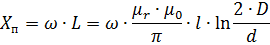
where ω — angular velocity, rad/s; L — linear inductance, H; μr — relative magnetic permeability of the medium; μo = 4π x 10 -7 — magnetic constant, H / m; l — line length, m; e — the distance between the conductors of the line, m.
For 1 km of line placed in air (μr = 1) at current frequency f = 50 Hz (ω=314 glad / and), the formula takes the form, Ohm / km,
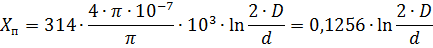
From this equation it can be seen that the external inductive resistance depends on the distance between the wires d and their diameter d... However, since d varies within insignificant limits, its influence is also insignificant and therefore Xn, depends mainly on d (the resistance increases with distance). Therefore, in order to reduce the external inductive resistance of the loop, the phase is zero, the neutral protective conductors must be laid together with the phase conductors or in close proximity to them.
For small values of e, commensurate with the diameter of the conductors e, that is, when the phase and neutral conductors are located in close proximity to each other, the resistance Xn is insignificant (not more than 0.1 Ohm / km) and can be neglected.
In practical calculations, they usually assume Xn = 0.6 Ohm / km, which corresponds to the distance between the conductors of 70 — 100 cm (approximately such distances are on overhead power lines from the neutral conductor to the farthest phase conductor).